
Traditional screw-terminal wiring requires a screwdriver and proper tightening to secure each conductor. A spring lever wire connector provides an alternative approach using a simpler motion: lift the lever, insert the wire, and press the lever down. This article explains what a spring lever wire connector is, how its internal parts work, the basic wiring steps, the main benefits, and where these connectors are commonly used.
What Is a Spring Lever Wire Connector?
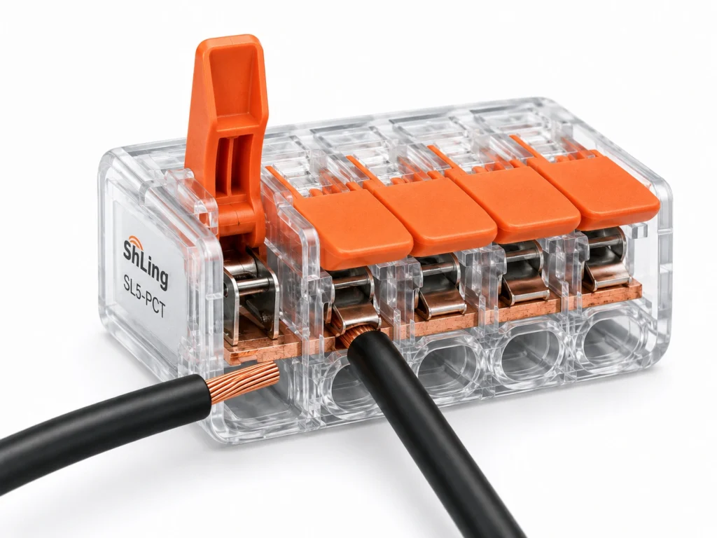
A spring lever wire connector is a screwless electrical wire connector that uses an operating lever and an internal spring to hold conductors in place. The lever opens and closes the clamping point; the spring applies continuous pressure to the conductor, and an internal conductive bar carries the current between wires.
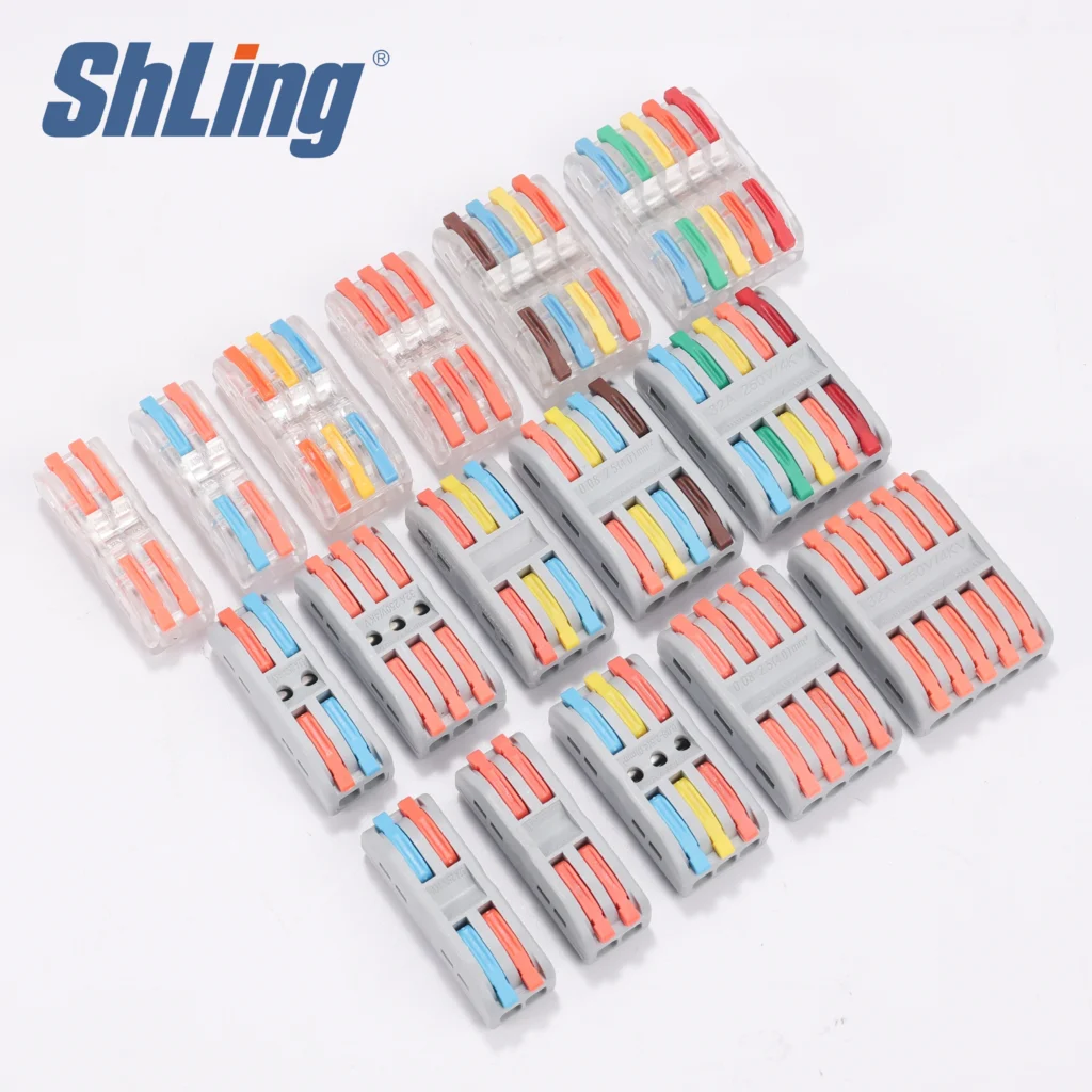
These connectors are often used to join, split, or branch two or more conductors of the same electrical potential. Common configurations include 2-port, 3-port, 4-port, 5-port, and 8-port versions. The number of ports refers to how many conductors can be inserted into one connector, not the number of poles. Because the ports inside a single connector are electrically connected, conductors at different potentials — such as line, neutral, and protective earth — must not be mixed within the same connector. Conductors at different potentials should be connected using separate connectors.
Not sure which configuration fits your project? Read our guide on how to choose the right PCT lever wire connector. A
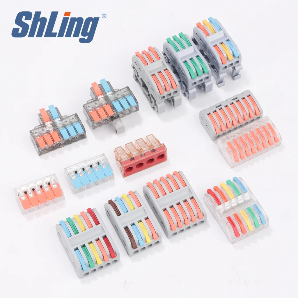
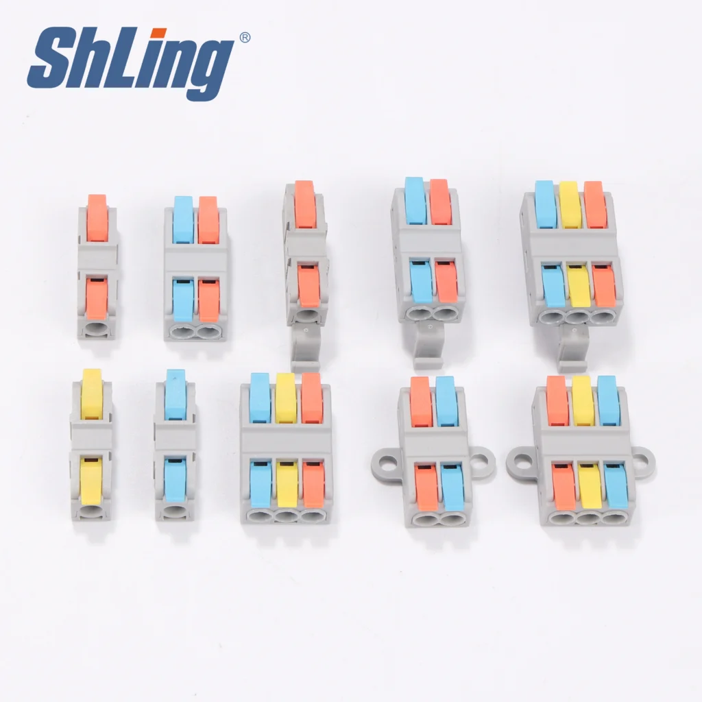
Why Is It Called a Spring-Clamp Connector?
The name comes from the way the connector holds a wire: a spring element applies clamping force to the conductor instead of a screw. This type of connection is also called a spring-clamp connection, a spring lever connection, or a lever-operated spring connection.
Some suppliers also describe this type of product as a spring-cage wire connector. The term “spring cage” generally refers to a compact internal clamping unit formed by the spring element and conductive contact. However, internal spring structures can vary between manufacturers. Therefore, “spring-clamp connector” or “spring lever wire connector” is often the safer generic description unless the exact spring-cage design has been confirmed.
Terminology Note
Lever wire connector describes the operating method, while spring-clamp connector describes the internal clamping principle. The term spring-cage connector may also be used for certain internal spring structures.
Operating Lever
The operating lever is the part the user moves by hand. Lifting it opens the internal clamping position so a conductor can be inserted or removed, and pressing it down lets the spring close onto the wire.
Spring Clamping Element
The spring clamping element is the metal part that presses against the conductor. Once the lever is closed, the spring maintains steady contact pressure so the wire stays fixed without additional tightening.
Conductive Contact Bar
The conductive contact bar carries current between the connected conductors. Its exact material should be confirmed according to the product specification.
Key Functional Elements of a Spring Lever Wire Connector
| Functional Element | Main Role | Simple Explanation |
|---|---|---|
| Operating Lever | Opens and closes the clamping point | Allows the conductor to be inserted or removed |
| Spring Clamping Element | Applies steady clamping pressure | Holds the conductor without screw tightening |
| Conductive Contact Bar | Carries current between connected conductors | Forms the electrical connection inside the connector |
The lever opens the connection point, the spring holds the conductor, and the conductive bar carries the current.
How Does a Lever Wire Connector Work?
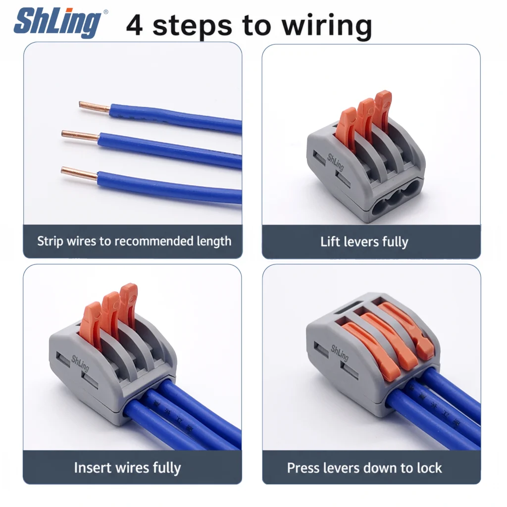
Wiring a spring lever wire connector involves four simple steps.
Step 1 — Strip the Wire
Remove the insulation according to the product’s specified stripping length. For the ShLing SL5-PCT series, the recommended strip length is 9–10 mm.
Step 2 — Lift the Lever
Raise the operating lever so the internal spring clamping position opens fully.
Step 3 — Insert the Conductor
Push the stripped conductor completely into the port until the insulation meets the housing. No bare copper should be left exposed outside the connector.
Step 4 — Close the Lever
Press the lever back down so the spring clamps the conductor against the internal contact bar. After wiring, give the wire a gentle pull to confirm it is held securely.
Main Benefits of Spring Lever Wire Connectors
Tool-Free Wiring
Because the spring provides the clamping force, a screwdriver is not needed to tighten a screw terminal. This reduces the number of tools required on site.
Faster Installation
The lift-insert-press sequence is quick to repeat, which helps speed up wiring in projects with many connection points.
Suitable for Different Conductor Types
Spring lever connectors can accept both solid and flexible stranded conductors, as long as the conductor size stays within the range specified for the product.
Easy to Disconnect and Reconnect
When a circuit needs to be adjusted or maintained, the lever can generally be reopened to release and reconnect the conductor, provided the connector is undamaged and used according to the product instructions.
Common Applications
Lighting Wiring — Used for suitable lighting branch connections, luminaire leads, drivers, and wiring inside canopies or junction boxes.
Junction Boxes — Used to join or branch conductors of the same electrical potential within the product’s rated range.
Distribution Boxes — May be used for suitable auxiliary or branch wiring, depending on the conductor size, current, voltage, and applicable installation requirements.
Control Cabinets — May support auxiliary wiring, lighting circuits, or other suitable internal connections within the connector’s rated specifications.
Household Appliances and Electrical Equipment — May be used for suitable internal wiring connections where the product ratings and installation requirements are met.
Explore more PCT lever wire connector applications in lighting, junction boxes, appliances, and electrical equipment. A
About the ShLing SL5-PCT Series
The ShLing SL5-PCT series is a range of lever wire connectors designed for quick, tool-free conductor connection.
The table below lists the main catalog specifications for the ShLing SL5-PCT series.
Main Catalog Specifications of the ShLing SL5-PCT Series
| Catalog Specification | ShLing SL5-PCT Series |
|---|---|
| Rated Voltage | 250 V |
| Rated Current | 32 A |
| Recommended Strip Length | 9–10 mm |
| Solid Conductor | 0.08–2.5 mm² |
| Flexible Stranded Conductor | 0.08–4.0 mm² |
| Available Wire Ports | 2, 3, 4, 5 and 8 |
| Connection Method | Lever-operated spring connection |
Actual suitability should be confirmed according to the conductor size, operating conditions, product specifications, and applicable electrical standards.
Basic Installation and Safety Notes
1. Disconnect the power before wiring.
2. Follow the specified stripping length.
3. Insert the conductor completely.
4. Do not exceed the rated current, voltage, or conductor range.
5. Keep conductors with different electrical potentials in separate connectors.
Conclusion
A spring lever wire connector relies on three key functional elements: the lever operates the connection point, the spring holds the conductor with steady pressure, and the conductive bar carries current between the connected wires. In suitable applications, this design provides an alternative to screw-terminal wiring and helps simplify installation, maintenance, and reconnection work. The ShLing SL5-PCT series offers 2-, 3-, 4-, 5-, and 8-port configurations to match different wiring needs. Contact ShLing to discuss conductor sizes, connector configurations, samples, and bulk order requirements for your wiring project.