Why Use a Pluggable Terminal Block?
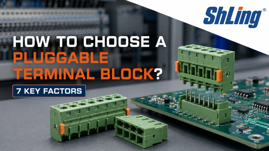
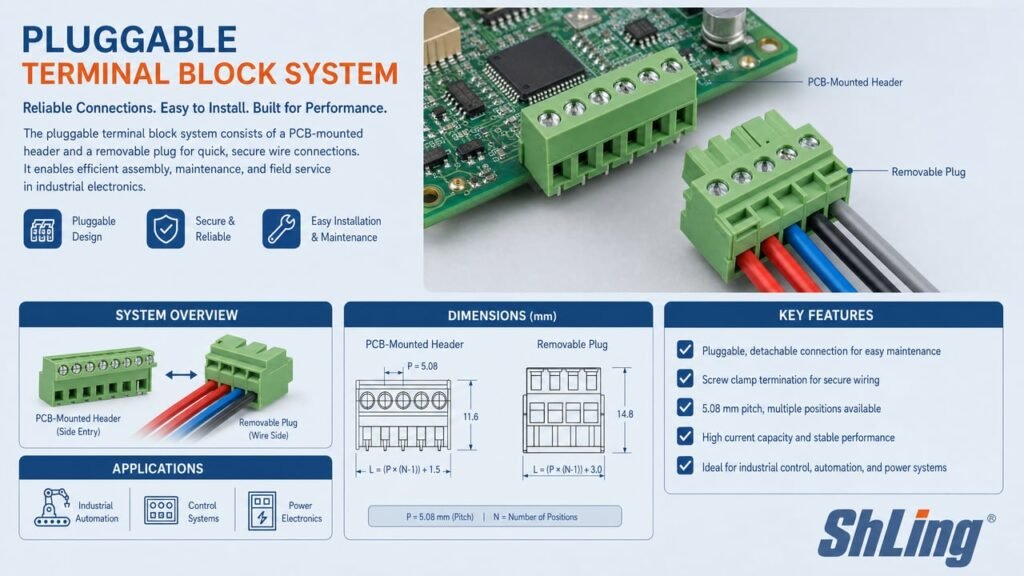
A pluggable terminal block splits the connection into two halves: a header soldered or clipped to the board (or rail), and a removable plug that carries the wires. That separation solves a problem screw-only terminals never fully addressed—maintaining a wired connection while letting you swap, inspect, or replace a module in seconds. In control cabinets where downtime costs money and in PCB designs where space shrinks every generation, that plug-and-socket architecture has become a standard choice.
But “pluggable” describes a category, not a specification. Within that category sit hundreds of pitch sizes, current ratings, locking mechanisms, and material grades. Pick the wrong combination and you get contact failure, overheating, or a connector that won’t survive its first vibration test. The factors below are the ones that actually determine whether a pluggable terminal block holds up in the field—or doesn’t.
Factor 1: Current and Voltage Rating
This is the non-negotiable starting point. A pluggable terminal block must carry the full load current of its circuit with a safety margin—not the nominal current, but the peak current under worst-case conditions. Manufacturers specify both a rated current and a rated voltage, and exceeding either risks overheating at the contact interface, accelerated insulation degradation, or dielectric breakdown.
Apply an appropriate design margin based on the applicable standard, operating temperature, simultaneous loading, conductor size, PCB layout, enclosure conditions, and the manufacturer’s derating curve. Do not rely on a fixed percentage alone. Rated current is typically specified under defined reference conditions (ambient temperature, single pole loaded, specific wire gauge). In real applications, multiple poles may carry current simultaneously, and ambient temperatures may exceed the reference value. Always consult the manufacturer’s derating curve, which accounts for ambient temperature, number of poles loaded simultaneously, wire cross-section, and PCB copper design. The actual allowable current must be obtained from the product-specific derating curve.
Rated voltage is the assigned operating voltage of the connector under specified insulation coordination conditions, including overvoltage category and pollution degree. Do not confuse rated voltage with impulse withstand voltage or dielectric test voltage. Manufacturers often provide different rated voltage values for different overvoltage categories and pollution degrees. Always confirm the rating that matches your application conditions from the datasheet.
Factor 2: Pitch, Footprint, and Plug-to-Header Compatibility
Pitch is one of the key parameters that constrains PCB layout, insulation spacing, and panel density. The dominant pitches for pluggable terminal blocks are 3.5 mm, 3.81 mm, 5.0 mm, and 5.08 mm. Larger pitches such as 7.5 mm and 7.62 mm are often selected when additional insulation spacing, larger conductors, or higher electrical ratings are required.
The pitch you choose is a compromise between density and creepage distance. A 3.5 mm pitch packs more poles into a given board edge, but the reduced spacing between conductors lowers the voltage the terminal can safely handle. A 5.08 mm pitch gives you more insulation between poles—important for higher voltages and harsher environments—but takes more board space. This is not a free parameter: it is locked in by your voltage requirement (Factor 1) and your board real estate budget simultaneously.
| Pitch | General Characteristics | Typical Selection Consideration |
| 3.5 / 3.81 mm | Compact spacing | Suitable when PCB space is limited; verify voltage rating, creepage distance, and wire range |
| 5.0 / 5.08 mm | Balanced size and wiring space | Common in industrial control and power-related PCB connections |
| 7.5 / 7.62 mm and above | Larger pole spacing | Often selected where additional insulation spacing, larger conductors, or higher electrical ratings are required |
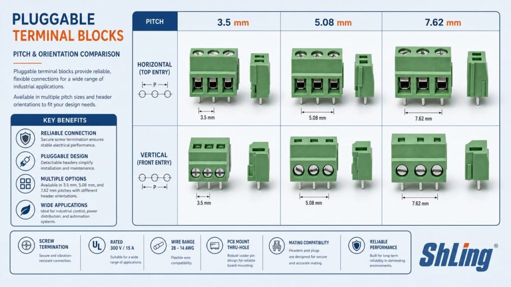
Important:Pitch alone does not determine rated current or rated voltage. Actual ratings depend on contact design and material, wire cross-section, terminal structure, ambient temperature, pollution degree, overvoltage category, creepage and clearance distances, PCB copper layout, and whether adjacent poles are simultaneously loaded. The same pitch can yield very different ratings across different product series. Always use the electrical ratings stated in the manufacturer’s datasheet for the exact plug-and-header combination.
A common mistake is assuming that any plug with the same pitch will mate with any header of that pitch. A reliable mating connection requires plugs and headers from the same product series or explicitly confirmed compatibility, matching pole count, compatible mating direction (horizontal 180° or vertical 90°), compatible contact specification, compatible locking structure, and matching coding keys where applicable. The 0.08 mm difference between 5.0 mm (metric) and 5.08 mm (imperial, 0.2 inch) means they are not truly interchangeable—mating across multiple poles can cause misalignment and contact issues.
Factor 3: Number of Poles
The number of poles determines how many individual circuits a single block handles. Pluggable terminal blocks are available in a wide range of pole counts, commonly including 2- to 24-pole versions, depending on the product series. More poles per block means fewer components on the board and fewer individual mating operations during assembly—but it also means that if one pole fails, the entire block must be replaced.
Think about the service angle. A 12-pole block saves panel space, but a technician pulling it in a cramped cabinet has to manage 12 wires simultaneously. For maintenance-intensive systems, dividing a long connector into smaller groups may simplify replacement, circuit identification, and troubleshooting. Match the pole count to your circuit topology, not to an arbitrary “more is better” impulse.
Factor 4: Wire Gauge Compatibility and Connection Method
A terminal block is only as good as the wire-to-plug connection it makes. Two connection technologies dominate the plug side:
Screw connection: The wire is secured by tightening a screw against a metal current bar. This is the established, proven method—robust, widely available, and tolerant of a range of wire types. The trade-off: it requires a screwdriver, takes more time per connection, and depends on the installer tightening to the correct torque. Undertighten and the contact resistance rises, the joint heats, and the insulation may melt; overtighten and you damage the conductor.
Spring cage / push-in connection: A spring mechanism grips the wire the moment it’s inserted—no tool, no screw to loosen over time. Push-in terminals accept solid or ferruled stranded wires directly; spring-cage types use a lever or pushbutton to open the clamp for stranded wire without ferrules. Connection speed is faster compared to screw types, and the spring maintains constant contact pressure even under vibration, reducing the creep-relaxation problem that can affect screw joints over years of thermal cycling.
The supported conductor range varies significantly by pitch, contact size, connection technology, and product series. Always verify the minimum and maximum solid, stranded, and ferruled conductor sizes in the datasheet. Using a wire smaller than the terminal’s minimum means the clamp can’t exert enough pressure; using a wire larger means it physically won’t fit. Both produce a connection that fails.
Factor 5: Locking Mechanism, Mating Cycles, and PCB Mounting
The plug-to-header interface is a critical potential failure point and should be evaluated for retention, contact stability, vibration, and mating durability. The plug is held in place by friction, a latch, or a screw—each with different reliability profiles.
Friction-only: The simplest design, where the plug is held by contact friction alone. Acceptable for low-vibration, rarely-serviced applications. Not recommended where the connector will see mechanical shock or frequent mating cycles.
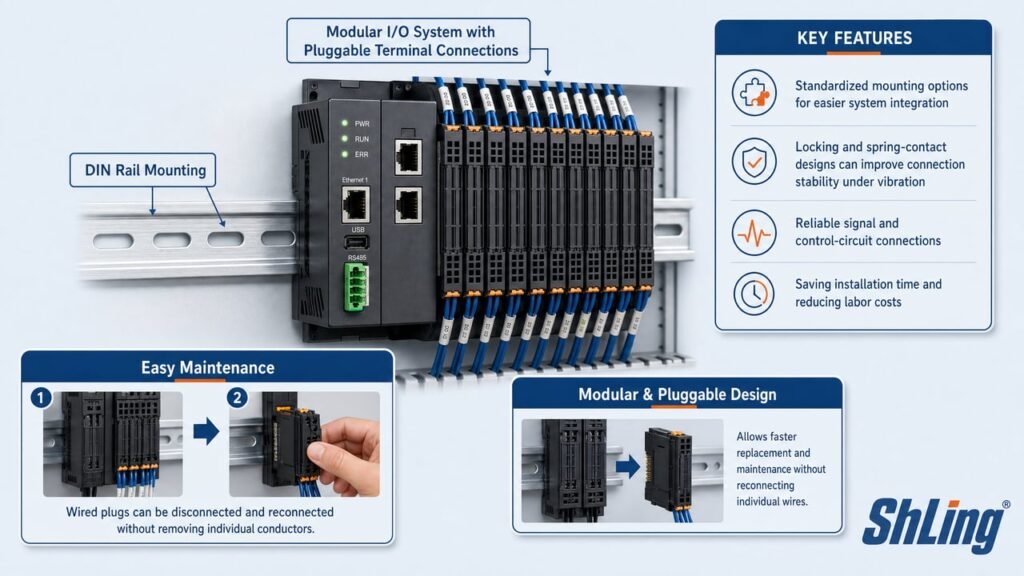
Latching mechanism: A spring-loaded latch (push-pull or side-lock) engages the header when the plug is inserted, providing a positive mechanical lock. Latching mechanisms provide additional mechanical retention and are suitable for applications exposed to vibration or mechanical shock. The actual insertion force and vibration rating should be confirmed from the manufacturer’s datasheet for the specific product.
Screw-locked plug: A screw-locked plug can provide strong mechanical retention, but it requires a tool and more time during mating and unmating. It is often selected for applications exposed to vibration, mechanical shock, or stricter retention requirements.
Mating cycles matter when the connector will be repeatedly unplugged—during production line testing, equipment servicing, or modular replacement. The permitted number of mating cycles varies significantly by product series, contact design, and surface plating. Many pluggable terminal block systems are rated for tens of mating cycles, while some specialized versions support higher cycle counts. There is no universal “industrial standard” cycle count. For applications requiring frequent mating cycles, select a contact finish specifically rated for the expected cycle count and operating environment. The exact value must be confirmed in the product datasheet.
Beyond the plug side, how the header mounts and solders to the PCB affects both manufacturability and long-term reliability. Headers are available in horizontal (180°) and vertical (90°) orientations, as well as with straight or angled pins—the choice depends on available board space, wire entry direction, and the clearance needed for plugging and unplugging. Confirm that the header is compatible with your PCB assembly process: wave soldering (most common for through-hole), manual soldering (prototypes or low-volume), THR/through-hole reflow (confirm the component is specified for this), or SMT surface mount (confirm solder pad layout and reflow profile compatibility). Verify that pin dimensions match the PCB plated through-hole specification, and that the connector’s plastic body can withstand your soldering temperature profile without deformation.
Safety Note
Unless the manufacturer explicitly specifies breaking capacity, do not connect or disconnect a pluggable terminal block while it is energized or carrying load. Pluggable terminal blocks are generally not designed as load-break switches. Isolate the power before mating, unmating, wiring, or servicing the connector.
Factor 6: Environmental Rating and Material Grade
A terminal block that works well in a climate-controlled PLC cabinet may not be suitable for an outdoor solar inverter or a food-processing plant with daily washdowns. The environment dictates several material and protection choices:
Insulator material: PA66 (polyamide 6.6) is widely used for terminal block housings, but its allowable operating temperature depends on the specific material formulation and product approval. High-temperature applications may require specially formulated engineering plastics or ceramic insulation. Always verify the rated operating temperature of the complete terminal block, rather than relying only on the generic material name.
Flame retardancy: UL 94 V-0 is a vertical flammability classification with limits on individual and total afterflame time, afterglow time, and flaming drips. It involves multiple evaluation criteria—not simply “10 seconds and no drips.” Verify the classification at the actual material thickness used in the terminal block housing, because a material’s UL 94 classification can vary with test thickness.
Ingress protection: The IP rating of a pluggable terminal block depends on the complete connector and enclosure system, not the terminal block alone. Standard PCB-mounted pluggable terminals are typically installed inside equipment enclosures, where the final IP rating is determined by the connector structure, equipment housing, sealing gaskets, panel-mount method, and fully mated state. For exposed outdoor or washdown applications, evaluate the complete connector and enclosure system. The IP rating may apply only when the plug and header are fully mated and installed with the specified seals or housing.
| Condition | Material / Protection | Consideration |
| Standard indoor | PA66, UL94 V-0, IP20 (within enclosure) | Meets baseline requirements for protected environments |
| Elevated temperature | Verify rated operating temperature of specific product | Do not assume temperature range from material name alone |
| Outdoor / humid | Evaluate complete connector + enclosure system | IP rating depends on fully mated state and specified seals |
| Vibration / shock | Latching plug + spring contact | Maintains contact pressure under dynamic load |
Factor 7: Standards, Approvals, and Regulatory Compliance
Standards and approvals tell you that a product has been evaluated against specific criteria. However, not all marks and standards serve the same purpose. Understanding the distinctions helps you make correct compliance decisions.
IEC 60947-7-1: Covers terminal blocks for copper conductors. This standard addresses rated current, voltage, mechanical strength, and short-circuit withstand for terminal blocks used in low-voltage switchgear and controlgear assemblies. It is a widely referenced standard for industrial terminal blocks.
IEC 60947-7-2: Specifically covers protective conductor terminal blocks with PE or PEN functions. This is a separate standard from IEC 60947-7-1 and should not be treated as interchangeable.
IEC 61984: For pluggable connector interfaces, this standard covers connectors with rated voltages above 50 V AC or 75 V DC and rated currents up to 125 A per contact. It may be more directly relevant to pluggable terminal blocks than IEC 60947-7, depending on the product design and intended application.
UL 1059 and CSA C22.2 No. 158: These are widely used standards for evaluating terminal blocks intended for North American equipment. Certification may be required by the end-product approval, customer specification, or local authority having jurisdiction. Whether a specific certification is mandatory depends on the product’s application, the end device, local regulations, and procurement requirements—some certification schemes are voluntary.
CE marking: CE marking applies only when the product falls within the scope of applicable EU harmonization legislation. For components such as terminal blocks, the applicability should be assessed according to how the component is marketed and used in the final equipment. CE marking is generally a manufacturer’s declaration of conformity with applicable EU directives—not a third-party certification or safety approval by an EU body.
RoHS / REACH: These are environmental and chemical substance regulations, not product safety certifications. RoHS restricts hazardous substances in electronic equipment; REACH addresses chemical registration, evaluation, and authorization. They are compliance requirements that apply alongside—not instead of—safety standards and certifications.
If you’re designing a product for global markets, look for terminal blocks that carry multiple approvals. This can simplify sourcing and compliance documentation—but always verify that the specific approvals match your end-product requirements and target markets.
Putting It Together: A Selection Checklist
| Factor | Key Question |
| Current & Voltage | What is my worst-case load current and system voltage? Have I consulted the derating curve for multi-pole loading at elevated ambient temperature? |
| Pitch & Compatibility | What pitch satisfies both my voltage creepage requirement and board space budget? Are the plug and header from the same product series with matching poles, direction, and locking? |
| Poles | How many circuits does this block need to handle, and does maintenance favor fewer poles per block? |
| Wire & Connection | What conductor sizes and types do I need? Is screw or spring-cage better for my assembly and maintenance context? |
| Locking, Cycles & Mounting | Will the connector see vibration? How many mating cycles over its service life? Is the header compatible with my PCB soldering process? |
| Environment | What temperature range, moisture level, and contamination will the block face? Have I evaluated the complete connector + enclosure system for IP rating? |
| Standards & Approvals | Which markets will this product ship to? What standards apply to the end product, and what component-level approvals are required? |
Frequently Asked Questions
Are pluggable terminal blocks interchangeable between different manufacturers?
Not necessarily. Even if two products share the same pitch, they may differ in contact design, locking mechanism, mating direction, and coding. Always verify compatibility in the manufacturer’s documentation. Using plugs and headers from the same product series is the safest approach.
Can pluggable terminal blocks be disconnected under load?
Generally, no. Unless the manufacturer explicitly specifies breaking capacity, pluggable terminal blocks are not designed as load-break switches. Disconnecting under load can cause arcing, contact damage, and safety hazards. Always isolate the power before mating or unmating.
What is the difference between 5.0 mm and 5.08 mm pitch?
5.08 mm corresponds to 0.2 inch and originated from imperial-standard designs. 5.0 mm is the metric equivalent commonly used in IEC-standard products. The 0.08 mm difference means they are not truly interchangeable—mating a 5.0 mm plug with a 5.08 mm header across multiple poles can cause misalignment and contact issues. Always use matching pitch values from the same product series.
Are screw-type and spring-cage plugs compatible with the same header?
Only if the manufacturer explicitly states compatibility. In most cases, plugs with different wire connection methods are designed as separate product families with their own matching headers. Do not assume cross-compatibility without manufacturer confirmation.
How many times can a pluggable terminal block be connected and disconnected?
This varies significantly by product series, contact design, and surface plating. Many pluggable terminal block systems are rated for tens of mating cycles, while some specialized versions support higher cycle counts. There is no universal “industrial standard” cycle count. The exact value must be confirmed in the product datasheet.
Choosing a Pluggable Terminal Block from ShLing
ShLing supplies pluggable PCB terminal blocks with different pitch, pole-count, connection, and mounting options. When requesting a quotation or sample, provide your working current, system voltage, conductor size, required pitch, pole count, mating direction, and applicable approval requirements. This information helps us identify a more suitable plug-and-header combination for your application.
The Bottom Line
Selecting a pluggable terminal block is not a single-variable optimization. Current rating, pitch, pole count, connection method, locking mechanism, material grade, regulatory compliance, plug-header compatibility, and PCB mounting compatibility all interact—your pitch constrains your voltage rating, your environment constrains your material, your mating cycle count constrains your contact plating, and your assembly process constrains your header type. The seven factors above give you the framework to work through those interactions systematically. When in doubt, consult the manufacturer’s datasheet for the specific product—and never assume that a generic parameter like pitch or material name is sufficient to make a selection decision.
References and Technical Notes
- IEC 60947-7-1 — Terminal blocks for copper conductors
- IEC 60947-7-2 — Protective conductor terminal blocks with PE or PEN functions
- IEC 61984 — Connectors with rated voltages above 50 V AC or 75 V DC
- UL 94 — Tests for flammability of plastic materials
- UL 1059 — Terminal blocks (North American standard)
- CSA C22.2 No. 158 — Terminal blocks (Canadian standard)
- EU CE marking official guidance (European Commission)
- RoHS Directive (2011/65/EU) and REACH Regulation (EC 1907/2006)
- Manufacturer product datasheets for specific ratings, derating curves, and mating cycle counts
Technical data in this article—including current/voltage ratings, mating cycle counts, temperature ranges, and material properties—are general references only. Always use the specific values stated in the manufacturer’s datasheet for the exact plug-and-header combination you intend to use.