Introduction
Screw terminal blocks create detachable electrical connections by using a screw-driven clamp to hold a conductor against a conductive element. They remain common because they accept many wiring layouts, are easy to inspect, and are available for DIN rails, printed circuit boards, barrier strips and panel feed-through interfaces.
This guide explains working principles, product types, materials, applications, standards, selection and installation. It is written for electrical engineers, OEM buyers, panel builders, contractors and equipment manufacturers who need to compare options without relying on unsupported performance claims.
What Is a Screw Terminal Block?
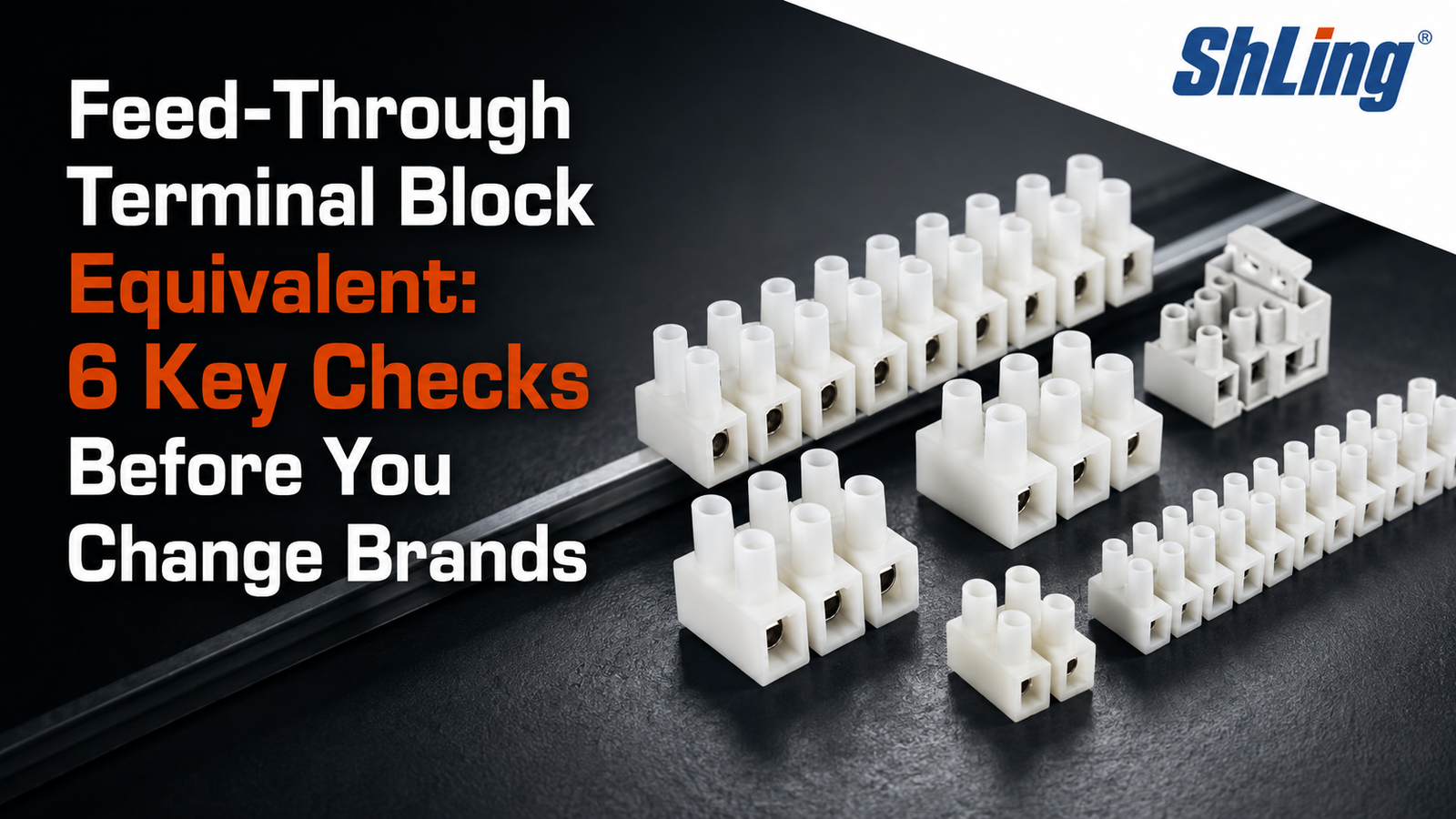
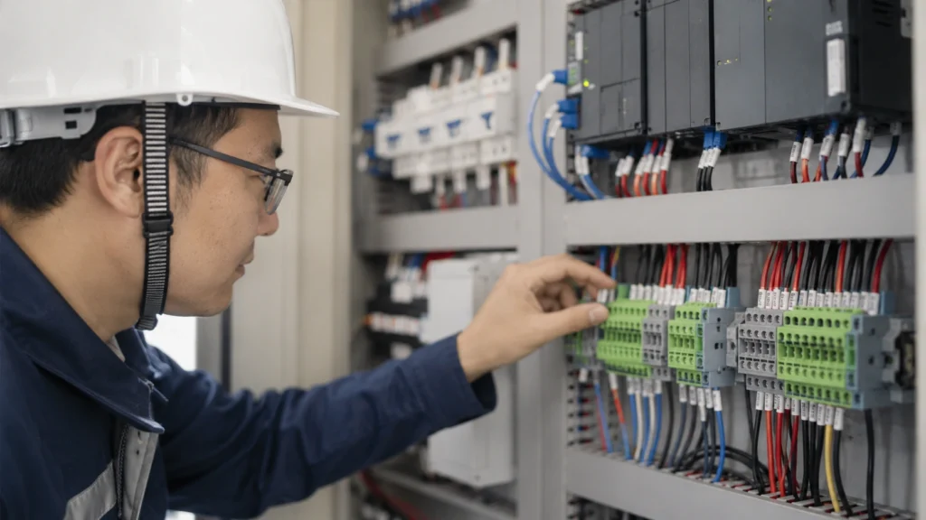
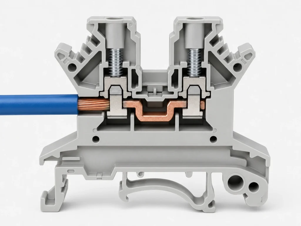
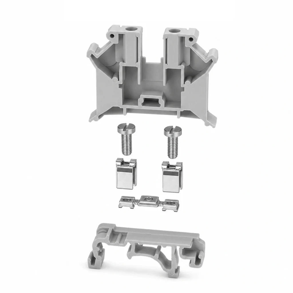
A screw terminal block is an insulated connection device that joins one or more conductors to a current-carrying path. A typical assembly includes an insulating housing, a screw, a pressure plate or wire cage, and a copper-alloy or brass current bar. Depending on the design, it may also include solder pins, mounting feet, barriers, test points, jumpers or marking areas.
Its primary job is to maintain electrical contact while providing mechanical retention, insulation and organized wiring. Product ratings and conductor ranges are model-specific; the terminal should never be selected from its appearance or nominal family name alone.
How Does a Screw Terminal Block Work?
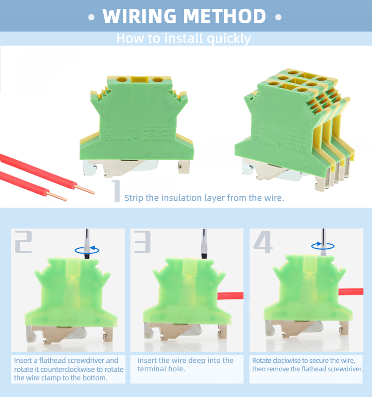
After insulation is stripped to the specified length, the conductor is inserted fully into the wire entry. Turning the screw moves a pressure plate or wire cage toward the current bar. The clamp distributes force across the conductor, and current passes through the metal contact interface into the conductive path.
Connection quality depends on contact area, conductor preparation, clamp geometry and tightening torque. Too little torque can leave a high-resistance or unstable joint; excessive torque can damage threads, deform the conductor or stress the housing. Stray strands, trapped insulation and an incorrect stripping length also reduce effective contact. Always use the value and method stated for the exact model.
Main Types of Screw Terminal Blocks
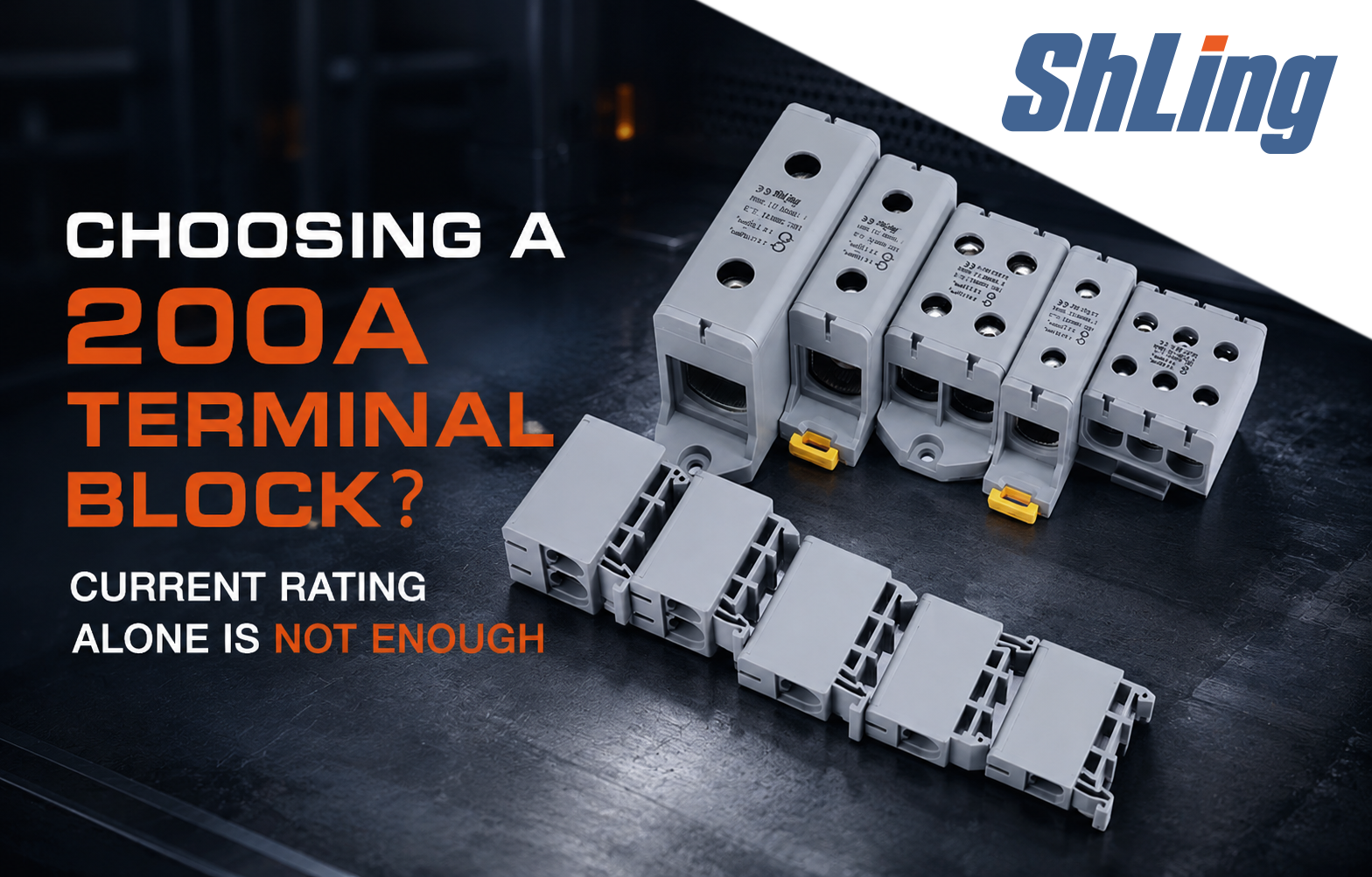
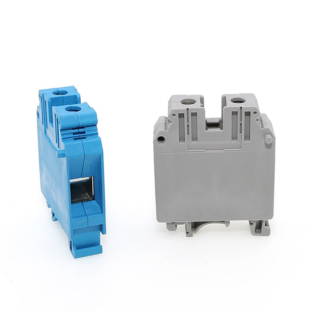
DIN Rail Screw Terminal Blocks
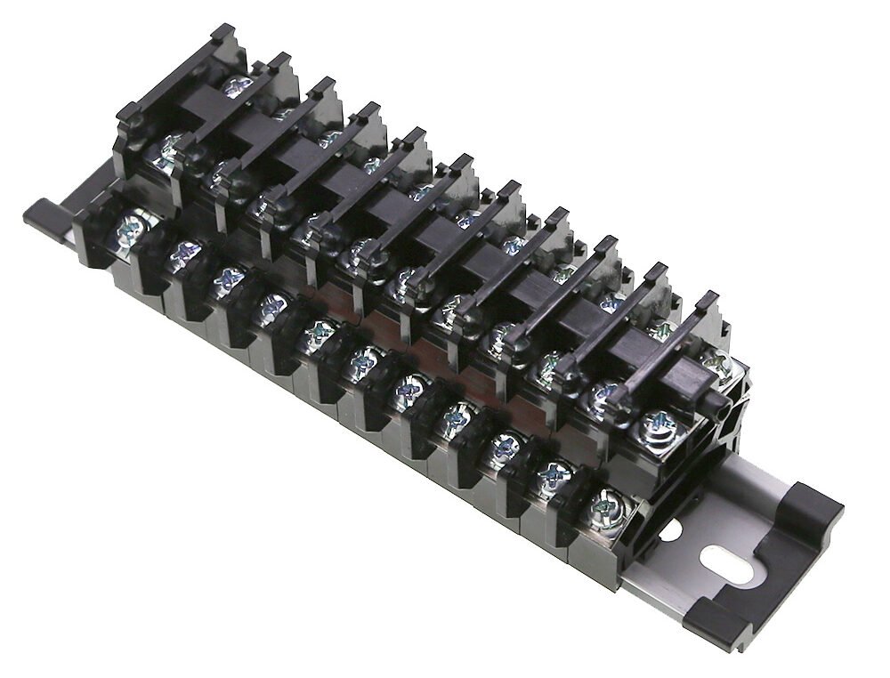
Mounted on standardized rail profiles for control cabinets and distribution panels. Feed-through versions connect conductors on opposite sides through an internal current bar. Rail dimensions may be standardized, but jumpers, end plates, markers, covers, partitions and end clamps are not necessarily interchangeable across manufacturers.
PCB Screw Terminal Blocks
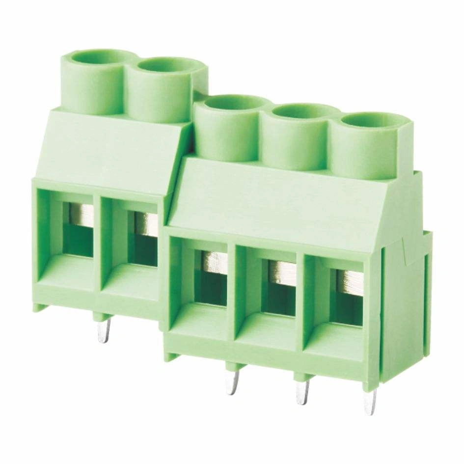
Used where field wiring must connect directly to a circuit board. The metal solder pins are inserted into PCB holes and soldered to the corresponding pads; the plastic housing is not a soldered part. Pitch, pin layout, current path, wave-solder profile and board spacing must match the PCB design.
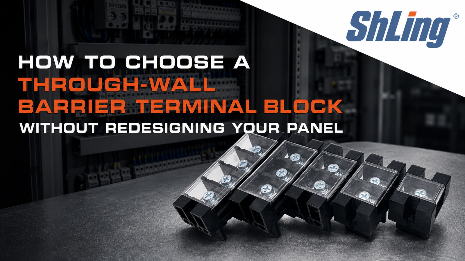
Barrier Terminal Blocks
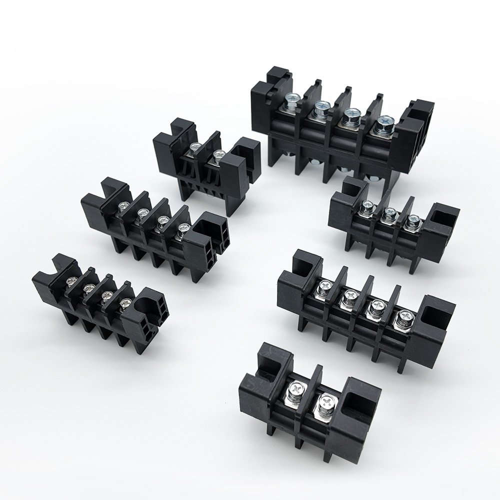
Insulating barriers separate adjacent poles and provide clear screw-access points. They are common in power supplies, appliances and equipment interfaces where ring or fork terminals may be used, subject to the product specification.
Panel Feed-Through Terminal Blocks
Designed to pass a connection through an enclosure wall or equipment panel. This differs from an ordinary feed-through rail terminal, which normally connects two sides within the terminal through a current bar. Confirm panel thickness, cutout, sealing and touch protection.
Comparison of Screw Terminal Block Types
| Terminal Block Type | Mounting Method | Typical Applications | Main Advantages | Key Selection Points |
|---|---|---|---|---|
| DIN rail screw | Clips to DIN rail | Control cabinets, distribution | Modular, organized wiring | Rail profile, wire range, accessories |
| PCB screw | Metal pins soldered to pads | Power supplies, controllers | Direct field-to-board interface | Pitch, pinout, process, spacing |
| Barrier | Panel/chassis or PCB, model-specific | Power equipment, appliances | Pole separation, accessible screws | Lug type, cover, spacing |
| Panel feed-through | Through enclosure panel | Enclosure interfaces | Inside/outside transition | Cutout, thickness, sealing, IP needs |
Multi-Level and Functional Terminal Blocks
Two- and three-level designs increase wiring density where cabinet space is limited; specialized products may use more complex arrangements. Functional variants include protective-earth, fuse, disconnect and indicator terminal blocks. Their circuits, markings, replacement components and test requirements must be checked individually.
Materials and Internal Structure
Insulating housings may use PA66, PBT, ceramic or other engineered materials. Their purpose is electrical insulation, mechanical support, maintenance of creepage and clearance, retention of conductive components, and protection against accidental contact. Actual temperature and flammability performance depend on the material grade, geometry and certified product construction—not the polymer name alone.
Current bars and cages commonly use brass or copper alloys; screws may be steel, and surfaces may be nickel- or tin-plated depending on the design. Alloy, plating thickness, surface condition and clamp geometry influence conductivity, corrosion behavior and long-term contact stability. Many metal parts and selected thermoplastics may be recyclable, depending on composition and local recovery systems.
Common Applications
They connect PLC I/O, sensors, relays, power supplies and field wiring. Modular DIN rail terminals support labeling and organized maintenance; verify control voltage, current, conductor range, cabinet density and accessory compatibility.
Industrial automation and control cabinets
Power distribution, inverters and renewable energy
They route control and power conductors between internal assemblies and external circuits. Confirm voltage category, current path, temperature rise, clearances, conductor type and environmental exposure; use approvals required by the destination market.
PCB power supplies and electronic equipment
PCB screw terminal blocks provide a serviceable field-wire interface for power supplies, lighting drivers and telecom equipment. Match pitch and pin layout to the board, and verify soldering process limits, wire-entry direction and enclosure access.
HVAC, appliances and transportation equipment
They connect motors, heaters, sensors, compressors and control boards where a screw-accessible joint supports assembly or service. Selection must reflect heat, vibration, moisture, corrosion and maintenance access; suitability for severe vibration requires model-specific evidence.
IEC, UL and NEMA Considerations
DIN describes a mounting format in many terminal-block contexts; it is not an alternative certification system to IEC or UL. IEC 60947-7-1 covers terminal blocks for copper conductors within its stated scope, while IEC 60999 addresses safety requirements for screw-type and screwless clamping units. UL 1059 is the UL standard titled Terminal Blocks. NEMA publications or equipment rules may also affect enclosure, installation and market expectations.
The same model can carry different IEC and UL voltage, current or conductor-range markings because rating methods and conditions differ. Never transfer a rating from one standard system to another. Check the exact part number, certification file, conditions of acceptability and current datasheet for the destination equipment and market.
How to Select the Right Screw Terminal Block
Start with the circuit and compliance envelope, then verify the conductor, mechanical interface and environment. A high current rating does not compensate for an incompatible wire range, insufficient clearance, wrong pitch or inaccessible screw direction. Build the selection around the complete assembly, not an isolated catalog value.
| Selection Parameter | What to Confirm | Why It Matters | Recommended Action |
|---|---|---|---|
| Rated current | Circuit load and applicable rating system | Affects heating and contact margin | Check exact-model datasheet and derating conditions |
| Rated voltage | Working voltage, category, clearances | Affects insulation coordination | Match equipment standard and market |
| Wire size | Permitted mm²/AWG range | Wrong size can clamp poorly | Verify solid/stranded limits in datasheet |
| Conductor type | Solid, stranded, flexible, ferrule need | Preparation depends on clamp design | Follow product and installation rules |
| Pitch and pole count | PCB/layout spacing and circuit count | Controls fit and isolation spacing | Check drawings and sample fit |
| Mounting method | DIN, PCB, panel, chassis | Defines mechanical interface | Confirm rail/profile/cutout/footprint |
| Wire entry direction | Top, side, front access | Affects assembly and service access | Review enclosure tool clearance |
| Stripping length | Exact value for part and wire | Too long or too short harms safety or contact | Use current datasheet; no universal value |
| Tightening torque | Specified tool and torque range | Under-torque or over-torque damages connection | Use calibrated torque tool as required |
| Housing and temperature | Material grade, operating limits, flammability | Material name alone is insufficient | Check certified construction and datasheet |
| Standards and approvals | Required IEC, UL, CSA, or market evidence | Ratings may differ by scheme | Verify exact part certification file |
| Accessories | Jumpers, markers, covers, end parts | Cross-brand interchange is not assured | Use approved matching accessory system |
| Environment | Vibration, corrosion, moisture, space | Changes mechanical and insulation needs | Request model-specific test evidence |
Installation Best Practices
- De-energize the circuit and verify the absence of voltage using an approved procedure.
- Confirm the conductor type and wire size against the exact product datasheet.
- Strip the conductor to the length specified in the terminal block datasheet. The required stripping length varies with terminal design and conductor size.
- Inspect the conductor for nicks, damage or loose strands; fit a ferrule only when required or permitted by the terminal and installation rules.
- Insert the conductor fully so no insulation is trapped in the metal contact area.
- Tighten with the specified tool and the manufacturer’s stated torque for that model.
- Perform a gentle pull check without exceeding the permitted mechanical load.
- After energizing, inspect temperature rise or connection condition where the equipment procedure requires it.
- During scheduled maintenance, look for looseness, corrosion, discoloration or overheating marks.
Common Installation Mistakes
- Stripping too long or too short
- Failing to insert the conductor fully
- Using too little or too much torque
- Clamping insulation inside the metal contact area
- Using a conductor outside the permitted range
- Leaving strands outside the clamp
- Adding or omitting a ferrule contrary to the datasheet
- Mixing incompatible accessories or connection systems
Frequently Asked Questions
What is a screw terminal block used for?
It creates an insulated, serviceable connection between conductors or between field wiring and equipment.
Can stranded wire be connected?
Yes, when the exact terminal is rated for that conductor type and size. Prevent stray strands and follow the preparation instructions.
Do screw terminal blocks require ferrules?
Not always. The need depends on clamp design, conductor, datasheet, installation standard and environment.
How tight should the screw be?
Use the torque specified for the exact model. Do not substitute a generic value.
Can screw terminal blocks be reused?
Only if the manufacturer permits it and inspection finds no damaged threads, clamp parts, housing or contact surfaces.
PCB terminal block vs. DIN rail terminal block?
A PCB type connects field wiring to board pads through solder pins; a DIN rail type clips to a rail and supports cabinet wiring.
How do I choose wire size?
Match circuit requirements to the exact model’s approved conductor range, including solid, stranded and ferruled conditions.
Are screw terminals suitable for vibration?
Some are, but suitability depends on clamp design, torque, anti-loosening features, conductor, testing and certification. Request model-specific evidence.