A light that flickers after installation is more than an annoyance. It may point to a loose conductor, an unsuitable connector, excessive voltage drop, or another fault that deserves attention. The small component joining the wires often determines whether a lighting circuit remains dependable or becomes a recurring service call.
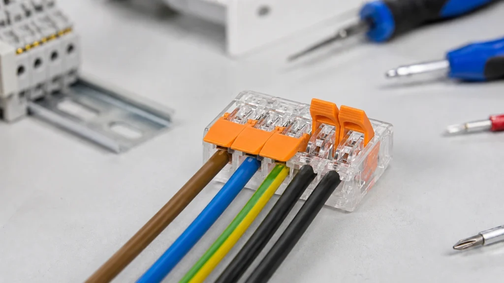
A lighting connector block provides a defined, insulated point for joining conductors in a luminaire, junction box, control panel, or low-voltage lighting system. Depending on its design, it may use screws, springs, levers, push-in clamps, or a plug-and-socket interface. The right block makes wiring easier to inspect, test, disconnect, and maintain. The wrong one—or the right one installed incorrectly—can create heat, arcing, or exposed live parts.
This guide explains how these connectors work, differ, and should be selected and installed. It serves beginners, contractors, OEMs, panel builders, and distributors.
Safety note: Electrical work can cause shock, fire, injury, or death. De-energize the circuit, prevent unintended re-energization, and verify absence of voltage with an appropriate tester before touching conductors. Mains-voltage work may require a licensed electrician, permits, inspection, and code-compliant enclosures. Always follow the connector, luminaire, and equipment manufacturers’ instructions and the rules enforced in your location.
What Is a Lighting Connector Block?
A lighting connector block is an insulated electrical connector that holds one or more conductors against a conductive metal element. It creates a controlled current path between the supply wiring and a light, driver, controller, or another section of the lighting circuit.
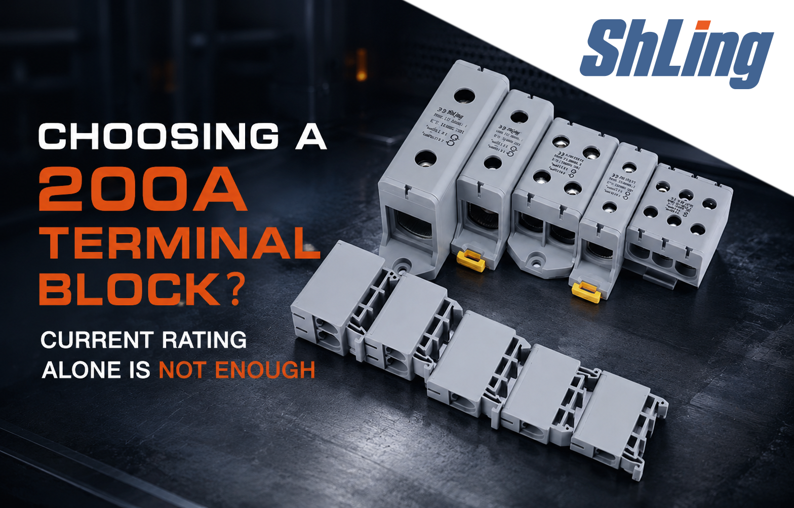
The phrase is not one universal product category. It can describe a screw terminal strip, a luminaire connector, a DIN-rail terminal, a pluggable fixture connector, or an LED distribution block. These products are not automatically interchangeable.
Most blocks contain three functional parts:
- A conductive element, usually a copper alloy, that carries current between connection points.
- A clamping mechanism that maintains contact pressure on each conductor.
- An insulating housing that separates poles and reduces accidental contact with energized metal.
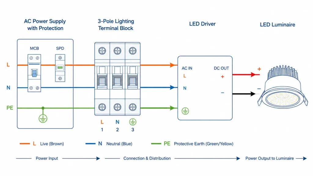
“Pole” and “position” describe separate electrical paths. A typical single-phase luminaire may need positions for line, neutral, and protective ground. A single-color low-voltage LED circuit may need positive and negative. RGB or RGBW lighting needs additional channels. A block with enough holes is not necessarily electrically arranged the way you need, so check which ports are internally common.
Connector block, terminal block, and wire connector: are they the same?
The terms overlap, but they are not exact synonyms. “Terminal block” is the broad industrial term for an insulated assembly that connects conductors. “Wire connector” includes many other devices, such as twist-on connectors and crimp splices. “Lighting connector” may refer to a connector optimized for joining solid building wire to a flexible luminaire lead. Product-specific LED connectors can be limited to one tape system or voltage.
For purchasing and compliance, the label matters less than the datasheet. Confirm the application, conductor range, electrical and temperature ratings, approvals, enclosure needs, and installation method.
How Does a Lighting Connector Block Work?
Electric current passes from one stripped conductor into the connector’s metal current bar and then into the connected conductor. Reliable performance depends on a low-resistance interface at both conductor contacts. The clamp must apply enough pressure to prevent movement and limit resistance without cutting, crushing, or otherwise damaging the conductor.
In a screw-clamp block, tightening a screw moves a pressure plate or clamp onto the wire. Some inexpensive barrier-free strips allow the screw to bear more directly on the conductor; whether a ferrule or other preparation is permitted depends on the terminal instructions. In a spring-clamp design, a shaped spring maintains pressure as conductors expand, contract, or experience vibration. A lever or push button opens the spring for insertion. A push-in connector uses conductor stiffness or a tool-assisted opening mechanism to engage the clamp.
The housing keeps separate potentials apart. This is why a connector’s voltage rating, creepage and clearance design, pollution assumptions, and enclosure instructions matter. A block acceptable inside a dry, closed luminaire is not automatically suitable for an exposed garden connection.
A simple lighting-circuit example
Consider a Class 2, 24 V DC driver feeding a single-color LED module. The driver’s positive output enters one pole and leaves for the LED positive input. The negative conductors use a separate pole. The block does not regulate current, reduce voltage, or protect against overload; it only creates the connection. The driver and circuit protection still have to suit the load and wiring.
For a mains luminaire, line, neutral, and protective-ground functions must remain correctly identified and separated. Never infer conductor function from position alone. Use the equipment diagram and verify the circuit. Some luminaires are double-insulated and have no equipment-grounding terminal; that does not mean existing grounding conductors should be cut off or repurposed.
Different Types of Lighting Connector Blocks
No single design wins every project. Choose based on conductor construction, production volume, service needs, space, vibration, environment, and the product’s evaluated conditions of use.
| Connector type | How it grips the wire | Best suited to | Main advantages | Important limitations |
|---|---|---|---|---|
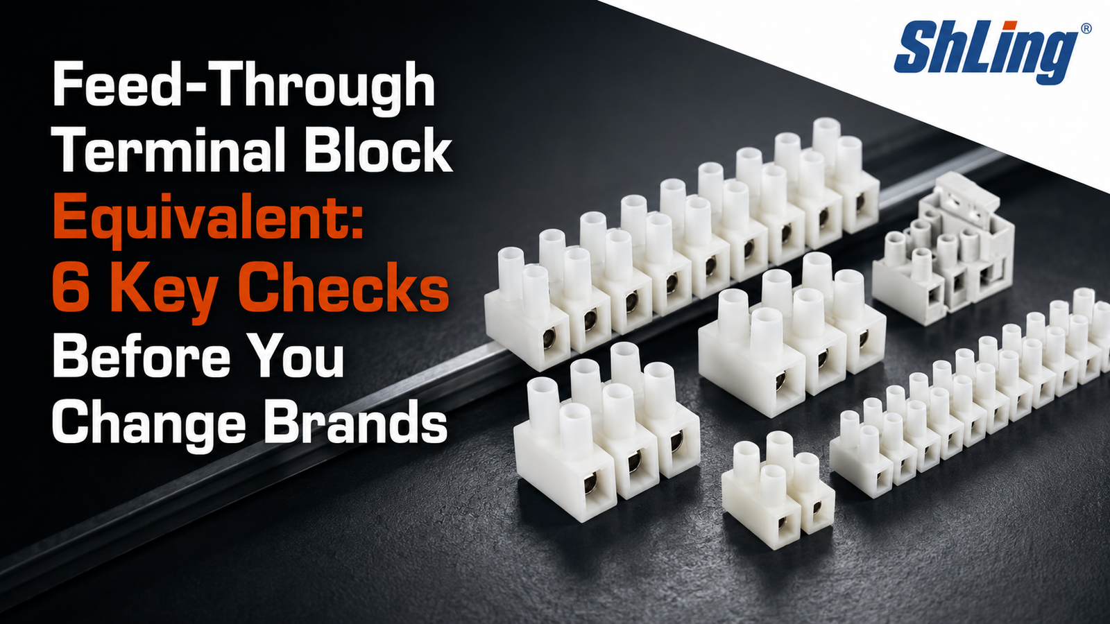
| Screw terminal strip | Screw and pressure plate or clamp | General fixture connections, prototypes, simple junctions | Familiar, reusable, easy to inspect, often cut to length | Requires correct torque; may loosen if poorly selected or installed; conductor preparation varies by model |
| Push-in connector | Conductor is pushed into a spring contact | Fast repetitive work with approved conductor types | Compact, quick, consistent, minimal tooling | Some ports accept solid wire only; release method and reusability vary |
| Lever or push-button spring connector | Lever or button opens a spring cage | Mixed solid and stranded wiring, serviceable fixtures | Fast visual workflow, easy replacement, spring pressure tolerates thermal cycling | Larger than some push-in designs; must be listed for the exact wire type and range |
| Luminaire connector | Separate supply and fixture sides, often spring-clamped | Joining solid installation wire to flexible fixture leads | Purpose-built transition, touch-protected designs available, quick fixture changes | The two sides may accept different conductor types or sizes |
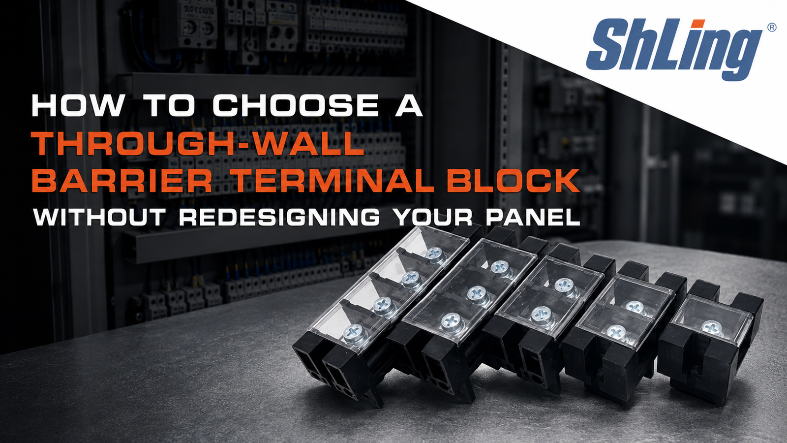
| Barrier terminal block | Screws separated by molded barriers | Panels, higher-current equipment, ring or fork terminals where approved | Clear circuit separation, labels and covers often available | Bulky; exposed studs may require a cover; terminal hardware must match the lug |
| DIN-rail terminal block | Screw, spring, or push-in element on a rail-mounted body | Lighting control cabinets and organized distribution | Modular, labelable, test-friendly, supports jumpers and accessories | Needs rail space, end stops, covers, and panel design discipline |
| Pluggable connector block | Mating plug and header or in-line male/female pair | Modular luminaires, prefabricated wiring, OEM assemblies | Fast commissioning and replacement; keyed versions reduce errors | Mating compatibility, current under load, touch safety, and mixed systems require careful control |
| LED distribution block | One input feeds several outputs | Cabinet, display, sign, and tape-light branches | Neat parallel distribution and quick expansion | Often proprietary and low-voltage only; total and per-port ratings both matter |
Screw-clamp blocks
Screw connectors remain useful because their state is visible and they accommodate many installation patterns. Their reliability depends on the specified strip length, wire preparation, and torque. Too little torque raises contact resistance; too much can damage the conductor, clamp, or housing. Do not put two wires under one screw unless the terminal is explicitly marked for that number and combination.
Spring, push-in, and lever blocks
Spring connectors speed assembly and maintain clamping force without a field torque step. However, “tool-free” does not mean “universal.” A push-in port may be evaluated for solid copper only, while a lever-operated port on the same device accepts fine-stranded wire. Tin-dipped ends, ferrules, and ultraflexible conductors are permitted only when the manufacturer says so.
Pluggable and modular blocks
Pluggable systems help when fixtures must be installed or replaced quickly. OEMs should control keying, pole count, mating cycles, strain relief, and connector families. A plug that fits is not proof of electrical compatibility.
Common Applications
Ceiling lights, downlights, and wall fixtures
A compact connector can transition from branch-circuit conductors to the flexible leads supplied with a luminaire. The connection normally belongs inside an approved luminaire canopy, outlet box, or other suitable enclosure, with conductor functions preserved and no copper exposed outside the connector.
LED strips, signs, and display lighting
Low-voltage systems use blocks between drivers, dimmers, controllers, splitters, and LED loads. A connector makes branch changes easier, but it cannot correct an undersized power supply or excessive cable voltage drop. For RGB and RGBW systems, label every channel and common conductor before disassembly.
Lighting control panels
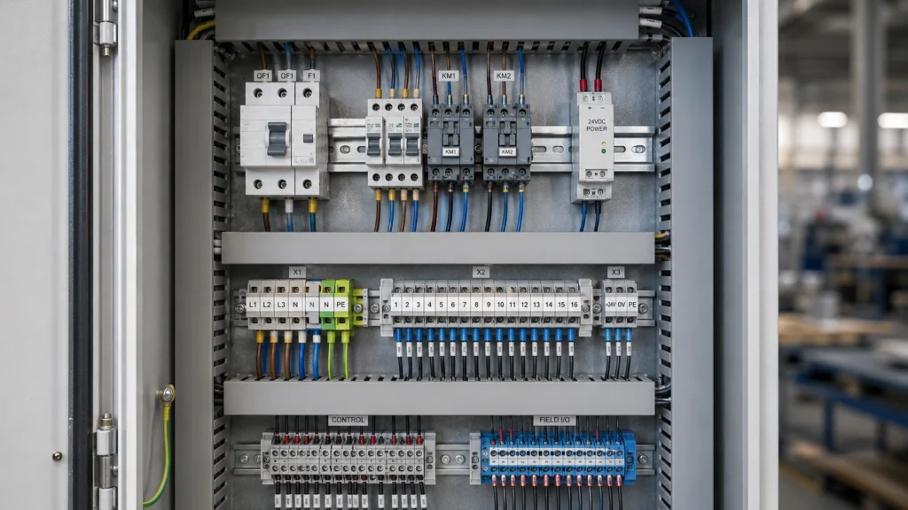
DIN-rail blocks organize incoming power, switched outputs, dimming pairs, sensor wiring, and protective conductors. Clear markers, separation of voltage classes, and accessible test points shorten commissioning and troubleshooting. Panel builders must also account for short-circuit ratings, temperature rise, spacing, and the requirements of the complete assembly.
Commercial and industrial luminaires
High-bay lights, machine lights, track systems, and emergency-lighting equipment may use pluggable or spring connectors for factory assembly and field service. Heat near LED drivers and vibration near machinery make temperature and mechanical ratings especially important.
OEM and prefabricated wiring
A standardized block can reduce OEM assembly time and wiring errors. Selection should include insertion force, test access, mistake-proofing, automation compatibility, traceability, approvals, and end-product certification.
Outdoor and damp-location lighting
Landscape, facade, greenhouse, and wash-down applications require a connection system evaluated for the actual moisture, dust, temperature, UV, and corrosion exposure. An indoor IP20 block placed inside a random plastic box does not automatically become a wet-location connection. Use a coordinated enclosure, cable entries, seals, and connector system approved for the location.
Advantages Over Traditional Wire Connections
Here, “traditional” means a hand-twisted splice covered with tape or another improvised twist, not a properly listed twist-on connector installed according to its instructions. Listed twist-on connectors remain valid for many applications. The meaningful comparison is between an improvised twist and a purpose-made connector—and between two listed methods selected for different service needs.
| Decision factor | Twisted wires with tape alone | Properly selected lighting connector block |
|---|---|---|
| Contact pressure | Depends on installer technique and may change over time | Controlled by a screw or spring mechanism |
| Insulation | Tape can shift, age, or leave an inconsistent finish | Molded housing provides defined separation and touch protection when used as instructed |
| Inspection | Hidden splice geometry is difficult to assess | Strip length, insertion, pole assignment, and clamp condition are easier to check |
| Rework | Untwisting can damage or shorten conductors | Many designs allow orderly disconnection and reconnection within their reuse limits |
| Multi-circuit organization | Becomes confusing as conductor count grows | Positions can be separated, labeled, and documented |
| Repeatability | Highly technique-dependent | Product-defined method supports consistent assembly |
| Suitability | Not an acceptable substitute where an approved connector is required | Can be compliant when listed or approved for the application and installed correctly |
They are not automatically safer merely because they look tidy. Safety still depends on product certification or approval, ratings, enclosure, conductor compatibility, workmanship, circuit protection, and code compliance.
How to Choose the Right Lighting Connector Block
Start with the system, not the connector catalog. Record the circuit voltage, maximum continuous and fault-related demands, conductor material and construction, wire size, number of poles, installation location, temperature, and service expectations.
1. Confirm voltage and current ratings
The connector’s marked voltage must equal or exceed the circuit voltage under its applicable approval and installation conditions. Its current rating must cover the expected load, but do not stop there. The conductor ampacity, driver output, branch protection, enclosure temperature, grouping, and applicable derating rules can impose lower limits.
For LED loads, calculate current rather than guessing from strip length. As a first estimate for a DC load:
Current (A) = Power (W) / Voltage (V)
A 72 W, 24 V load draws about 3 A before allowing for design margin and system details. If four branches share one distribution block, check both each output rating and the block’s total input rating. For mains LED drivers, inrush current can affect switching and protective-device selection even when steady-state current is modest.
2. Match every conductor characteristic
Check the permitted AWG or square-millimeter range, copper or aluminum marking, solid or stranded construction, strand class, temperature rating, and required preparation. Never assume that a hole large enough for the wire is approved for it.
Fine-stranded conductors may need a ferrule in some screw terminals. Other terminals accept bare fine-stranded wire and specifically prohibit solder-tinned ends. Solder can creep under pressure, reducing clamp force. Use ferrules only when the connector instructions allow them, and crimp them with the specified profile and tool.
3. Select the correct pole arrangement
Count independent electrical paths, not physical openings. Typical needs include two poles for single-color DC, three for single-phase line/neutral/protective ground, and four or five for multichannel LED systems. Protective-conductor terminals may have special color, bonding, or rail-contact requirements. Never use green-yellow identification for another function.
4. Evaluate the environment
Compare ambient temperature, heat from drivers or lamps, humidity, condensation, dust, vibration, chemicals, salt, and UV exposure against the product data. Confirm the enclosure’s ingress-protection or NEMA-type suitability as a complete installed system, including cable glands and unused openings.
5. Check approvals and end-use conditions
For North American projects, look for certification appropriate to the connector and end use, then verify its conditions of acceptability. For international industrial equipment, IEC 60947-7-1 covers certain terminal blocks for copper conductors; household and luminaire connectors may fall under other standards. CE marking is not a substitute for an independent safety certification, and RoHS addresses restricted substances rather than electrical connection safety.
The authority having jurisdiction and the finished equipment determine what is acceptable. Ask for a current datasheet, certificate or file reference, installation instructions, and declaration information relevant to the destination market.
6. Consider installation and lifecycle cost
A lower component price can be erased by slow wiring, special tooling, rework, or difficult service. Compare preparation, insertion time, torque control, test access, labeling, and training. OEM buyers should also consider traceability, availability, and supplier change control.
| Application | Recommended connector type | Typical connector current class to evaluate* | Common wire-size range to evaluate* |
|---|---|---|---|
| Single decorative 12/24 V LED branch | Two-pole spring or approved LED connector | 3-10 A | 22-16 AWG (0.34-1.5 mm²) |
| RGB/RGBW LED wiring | Four- or five-pole pluggable/spring connector | 3-10 A per applicable common path | 22-16 AWG (0.34-1.5 mm²) |
| Ceiling luminaire connection | Purpose-built luminaire connector | 6-24 A | 20-14 AWG (0.5-2.5 mm²) |
| Commercial fixture whip | Lever/spring or pluggable lighting connector | 10-20 A | 18-12 AWG (0.75-4 mm²) |
| Lighting control cabinet | DIN-rail terminal block | 10-30 A | 18-10 AWG (0.75-6 mm²) |
| Multi-branch low-voltage distribution | Fused or unfused distribution block as design requires | Sum of all branches plus design margin | Based on feeder and branch ampacity |
| Damp or outdoor location | Sealed in-line connector or approved block-and- enclosure system | Load-specific | Cable- and seal-specific |
Installation Tips
Installation instructions take priority over generic advice. The following workflow helps prevent common errors without replacing product-specific requirements.
Plan and make the circuit safe
Identify every energy source, including emergency supplies, batteries, and control feeds. Isolate the correct circuit, apply lockout/tagout where required, and verify absence of voltage with a properly rated tester. If you are not qualified to do this, hire a licensed professional.
Read the wiring diagram. Photograph and label existing conductors before disconnecting them, but do not rely on color alone. Confirm whether the circuit is AC or DC, the polarity or conductor functions, and where the connection must be enclosed.
Prepare conductors accurately
Use a stripping tool sized for the conductor. Strip exactly the length shown on the connector or datasheet. Nicked strands reduce cross-sectional area; missing strands and uneven ends can create a poor clamp. Do not leave insulation inside the current-carrying contact or bare copper outside the housing.
Keep stranded wire compact without overtwisting it. Add a ferrule only if permitted and needed. Do not solder-tin a conductor end unless the terminal documentation explicitly approves that preparation.
Insert and clamp correctly
Open a lever or push button fully where applicable. Insert the conductor to the stop and make sure no insulation is trapped in the clamp. For screw terminals, use the specified screwdriver and calibrated torque tool when a torque value is provided. Do not estimate torque by feel on safety-critical production work.
Give each wire a controlled tug to confirm retention. Check that the correct conductor entered the correct pole, strands are not splayed, and no copper is visible beyond the housing. Fit covers, partitions, end plates, markers, and strain relief required by the system.
Enclose, test, and document
Place the completed connection in its approved enclosure without forcing sharp bends or putting tension on the terminal. Maintain separation from heat sources and between voltage classes. Close unused cable entries with approved plugs.
Before energizing, perform the inspections and electrical tests required for the work and local rules. A qualified person may need to verify protective-conductor continuity, insulation resistance, polarity, and operation. Investigate flicker, odor, noise, or unexpected heating immediately.
Common Mistakes to Avoid
Treating the amp rating as the whole design
A “20 A” block is not automatically suitable for every 20 A circuit. Approval conditions, conductor size, ambient temperature, grouping, enclosure heat, and circuit protection all matter. Use the lowest applicable limit in the complete system.
Mixing conductor types without approval
Solid, stranded, fine-stranded, aluminum, copper, ferruled, and tinned conductors behave differently under pressure. Use only combinations shown in the instructions. Never mix copper and aluminum in a connector unless it is identified for that combination and installed with all required preparation.
Putting multiple wires in one opening
Unless a terminal is marked for multiple conductors of the stated sizes and types, assume one conductor per clamping point. Two wires can clamp unevenly, leaving one loose even when the screw feels tight.
Stripping too much or too little insulation
Too little stripping can clamp insulation instead of metal. Too much leaves exposed copper and reduces touch protection. Use the strip-length gauge molded into the connector when provided.
Confusing parallel distribution with series wiring
Many lighting distribution blocks place outputs in parallel, so each branch receives the same supply voltage. Do not assume internal connections from the shape of the block. Check the diagram or verify continuity while de-energized.
Omitting strain relief and an enclosure
The electrical clamp may not be designed to carry cable pull. Use the required cord grip, cable clamp, gland, or fixture strain relief. Keep connectors inside a suitable box or housing unless the product is specifically approved for unenclosed use.
Reusing damaged or single-use connectors
Heat discoloration, cracked plastic, weak springs, damaged screws, and deformed ports are replacement signals. Some push-in connectors are not intended for repeated reuse. Follow the declared mating or reuse limits.
Working live because the job “only takes a minute”
Compact lighting circuits can still deliver lethal mains voltage or high fault current. Controls and emergency systems can energize unexpectedly. De-energization and verification are part of the job, not optional setup.
Maintenance Tips
Maintenance should follow the equipment instructions and reflect the environment and duty—not a habit of tightening every screw on a calendar.
During de-energized inspection, look for discoloration, brittle insulation, corrosion, moisture, loose housings, damaged strain relief, conductor movement, and odor. Check labels, covers, glands, and panel hardware.
Do not routinely retorque a connection unless the manufacturer or maintenance plan calls for it. Unnecessary tightening can damage terminals, and any torque check must follow the prescribed method. If thermal imaging is part of a qualified maintenance program, compare similar loaded connections and investigate abnormal temperature differences; a thermal image alone does not diagnose the cause.
Replace a connector that has overheated. Do not merely clean it and reconnect the wire: heat can weaken the spring, anneal the conductor, damage plating, and degrade the housing. Find and correct the underlying cause, then trim back or replace heat-damaged conductor as appropriate.
Frequently Asked Questions
1. What is a lighting connector block used for?
It creates an insulated, mechanically controlled connection between conductors in a lighting circuit. Common uses include joining supply wiring to luminaire leads, connecting drivers to LEDs, organizing control-panel wiring, and distributing low-voltage power to several lighting branches.
2. Is a lighting connector block the same as a terminal block?
Often, but not always. A lighting connector block is generally a terminal block or wire connector used or optimized for lighting. Some are purpose-built to join solid installation wire to flexible fixture wire, while others are generic strips, DIN-rail terminals, or proprietary LED distribution connectors. The datasheet defines the product.
3. Can I use a lighting connector block for mains voltage?
Only if the specific connector is rated and approved for the circuit voltage, conductor, enclosure, temperature, and end use, and local rules permit it. A block sold for 12/24 V LED tape may be unsuitable for branch-circuit wiring even if it looks similar.
4. Which connector is best for stranded fixture wire?
A spring, lever, push-button, or screw terminal explicitly approved for the strand class and wire size can work. Some luminaire connectors have one port for solid building wire and another for stranded fixture leads. Do not force stranded wire into a solid-only push-in port.
5. Do stranded wires need ferrules in a connector block?
It depends on the terminal. Ferrules can improve handling and strand containment in compatible terminals, but they alter the termination and are not universally required or permitted. Follow the connector maker’s instructions for ferrule type, length, size, and crimp profile.
6. Can two wires share one terminal opening?
Only when the terminal is identified for that exact number, material, type, and size combination. Otherwise, use separate connection points and an approved jumper or distribution method. A physically roomy opening does not establish approval.
7. How much insulation should I strip?
Use the length marked on the connector or stated in its instructions. Many compact lighting connectors use roughly 9-11 mm, but that is not universal. A built-in strip gauge is the safest quick reference for that model.
8. Why does a connector block get hot?
Possible causes include a loose or contaminated contact, wrong wire size or type, incomplete insertion, excessive current, damaged strands, corrosion, high ambient temperature, or a degraded connector. De-energize the circuit and have the complete connection assessed. Do not keep operating an overheating joint.
9. Are connector blocks reusable?
Some are designed for repeated disconnection; others have limited or no reuse. Screw, lever, and pluggable designs are often serviceable within specified limits, while certain push-in products are single-use. Replace any connector that is worn, damaged, overheated, or outside its declared reuse conditions.
10. Can a connector block be left exposed above a ceiling?
Usually, a mains connection must remain inside an approved, accessible enclosure or a connector system specifically evaluated for that installation method. Concealed-space and accessibility rules vary by jurisdiction. Follow the equipment instructions and local electrical code, and ask the authority having jurisdiction when uncertain.
Conclusion
A lighting connector block is simple in purpose but consequential in practice. It carries current through a controlled mechanical contact while insulating and organizing the connection. The most important selection questions are not “Which block looks right?” or “Which has the biggest amp number?” They are: Is it approved for this voltage, load, conductor, environment, enclosure, and end use—and can it be installed exactly as instructed?
For a small LED project, that may lead to a two-pole spring connector. For a ceiling fixture, it may be a purpose-built luminaire connector with different supply and fixture ports. For a control cabinet, it may be a labeled DIN-rail system with test accessories. In every case, accurate stripping, full insertion, correct clamping, strain relief, enclosure, testing, and documentation turn a small component into a dependable connection.
When the requirements are unclear, pause before energizing. A product datasheet, a qualified electrician, and the local authority having jurisdiction are far less costly than troubleshooting a damaged lighting system later.