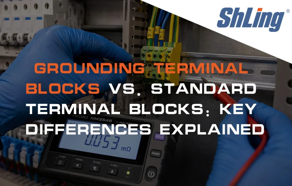
Quick Answer: Grounding terminal blocks are used for protective earth (PE) connections, while standard terminal blocks carry power, control, or signal circuits. The decisive difference is the connection to the DIN rail: a true grounding terminal has a conductive metal base that bonds the PE conductor to the rail and cabinet grounding system. A standard terminal keeps its conductor electrically isolated from the rail. The two types are not interchangeable, and a standard terminal must not replace a grounding terminal in a PE circuit.
What Is a Grounding Terminal Block?
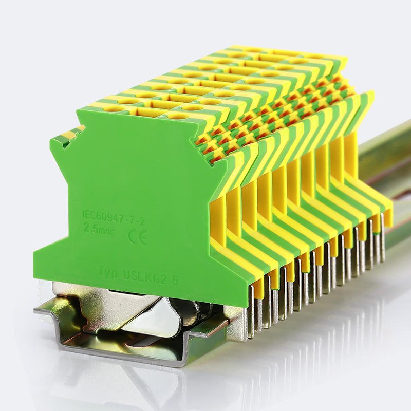
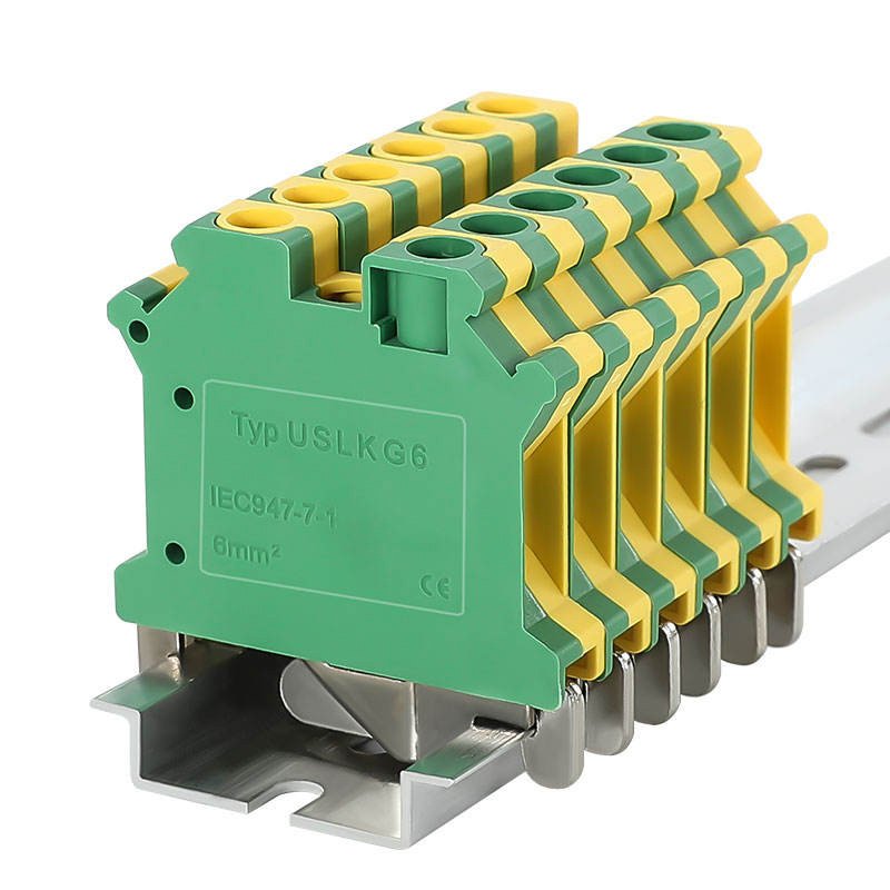
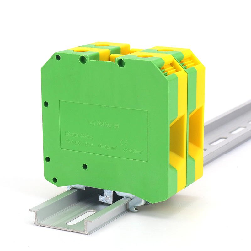
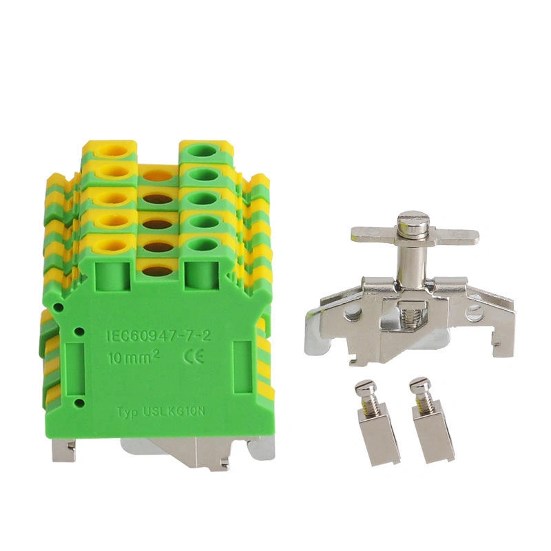
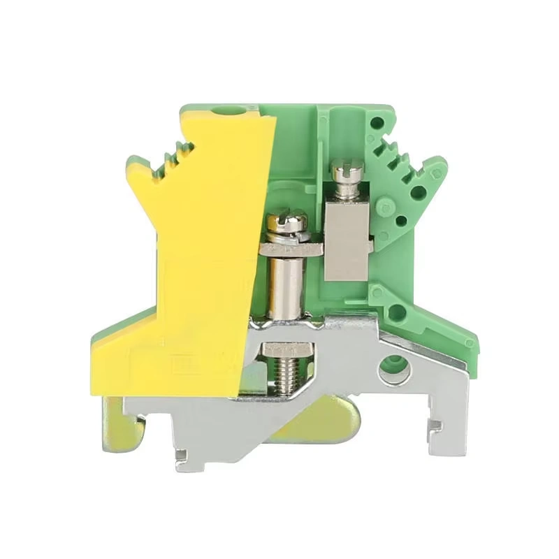
A grounding terminal block, also called a PE terminal block, terminates a protective earth conductor and creates an electrically conductive connection to the DIN rail. Its clamping mechanism holds the conductor, while a conductive metal foot or base contacts the rail directly.
When the DIN rail is correctly bonded to the cabinet grounding system, the terminal helps form a continuous, low-resistance path for fault current. This path supports the operation of upstream protective devices and helps reduce hazardous touch voltage.
Key Takeaway: A grounding terminal block creates a low-resistance path between the PE conductor, the DIN rail, and the cabinet grounding system.
What Is a Standard Terminal Block?
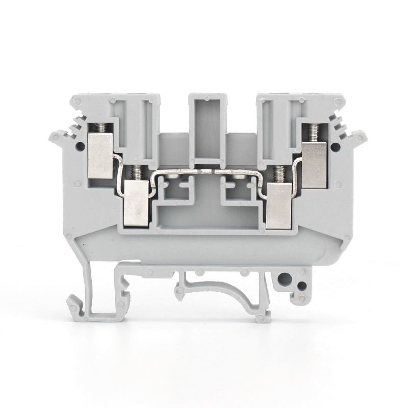
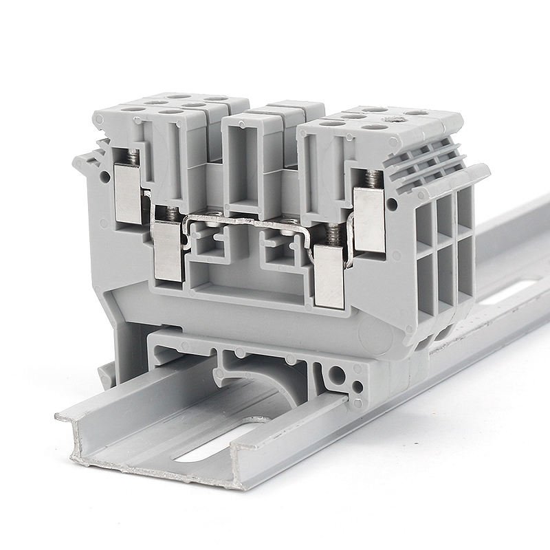
A standard feed-through terminal block connects two conductors so power, control voltage, or a signal can pass through its internal current bar. Its insulated housing keeps the current path separate from the DIN rail.
Standard terminals are used throughout control cabinets for power distribution, PLC and I/O wiring, sensor circuits, relay connections, and other operating circuits. Their purpose is circuit continuity between conductors—not protective bonding to the mounting rail.
Tip: Standard terminal blocks may look similar to grounding terminal blocks, but their insulated housing keeps the conductor electrically isolated from the DIN rail.
Key Differences at a Glance
| Function | Grounding Terminal Block | Standard Terminal Block |
|---|---|---|
| Primary function | Protective earth and bonding | Power, signal, or control continuity |
| DIN rail connection | Direct conductive connection through a metal foot/base | Electrically isolated by the housing |
| Current path | PE conductor to rail and cabinet grounding system | Input conductor to internal current bar to output conductor |
| Housing color | Typically green-yellow with PE marking | Commonly grey; blue, orange, red, black, white, or beige may be used by function |
| Typical use | PE, equipment bonding, selected shield and surge-ground connections | 24 VDC, PLC/I/O, sensors, relays, and instrumentation |
| Safety role | Provides the protective fault-current path | Carries the normal operating circuit |
| Can it be used for PE? | Yes, when specified and installed as a PE terminal | No; a standard insulated terminal does not bond the conductor to the rail |
Structure Difference: Metal Foot vs. Insulated Housing
Both terminal types may use screw-clamp, spring-clamp, or push-in connection technology. They may also accept similar conductor sizes and require comparable tightening practices. The critical difference is underneath the clamping mechanism.
A grounding terminal uses a stamped or machined metal support—commonly plated steel or tinned copper, depending on the product design—that extends through the housing and presses against the DIN rail. This metal-to-metal interface connects the PE conductor to the rail.
A standard feed-through terminal typically uses an insulating PA 6.6 housing around its current-carrying parts. Product-specific flame-retardant and electrical ratings, including any UL 94 classification, must be confirmed in the manufacturer datasheet.
Some manufacturers publish very low contact-resistance values for correctly installed PE terminals. The original source cites a value of 0.5 mΩ or less for certain products; this is product-specific and requires verification against the exact manufacturer datasheet before publication or design use. Source needed.
Warning: Never assume a terminal block is suitable for grounding only because it has a similar shape or color. A real grounding terminal block must have a conductive metal base that connects to the DIN rail.
Current Path: Two Completely Different Circuits
Grounding Terminal Block
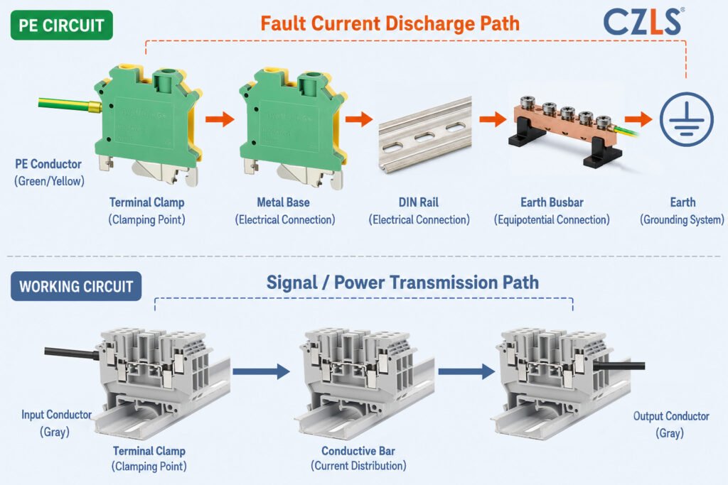
PE conductor -> clamp -> metal base -> DIN rail -> cabinet grounding system -> earth
Standard Terminal Block
Input conductor -> clamp -> current bar -> output conductor
The standard terminal transfers operating current or a signal between conductors. The grounding terminal serves a different electrical role: it creates a path for protective bonding and fault current. This is not a matter of one terminal having more features; the circuits are fundamentally different.
Color Coding: Green-Yellow Is Not Decoration
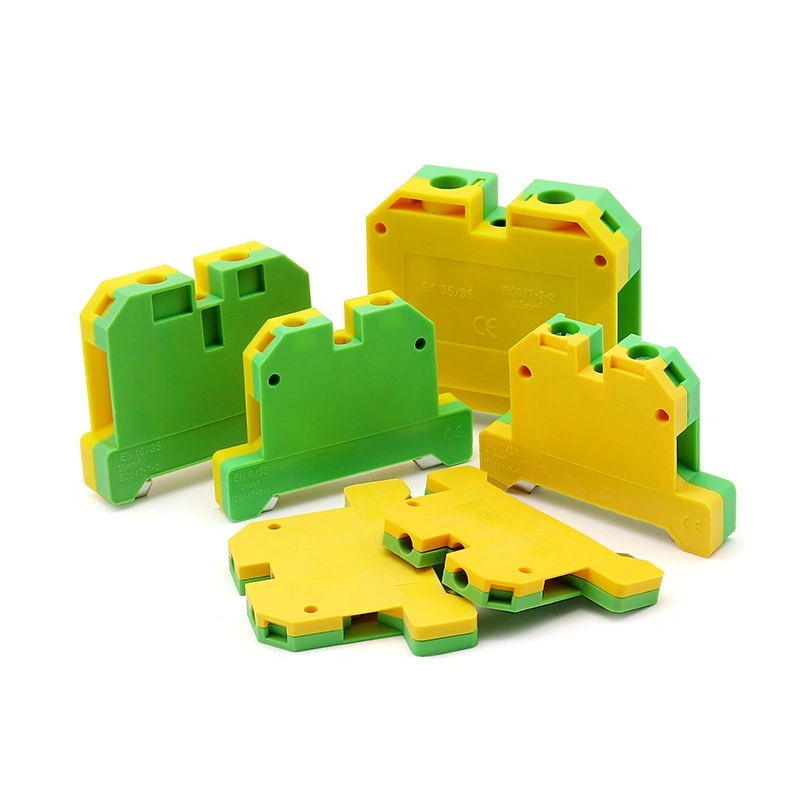
Green-yellow identification is reserved for protective earth conductors and terminals under applicable IEC identification practices. A compliant PE terminal should also carry the appropriate protective earth symbol, commonly referenced as IEC 60417-5019. Always verify the marking requirements that apply to the destination market and equipment standard.
Standard terminals use a wider color range. Grey or beige is commonly used for general power and signal wiring; blue is commonly associated with neutral conductors; and orange or red may identify circuits that remain energized after a main disconnect. Black and white may also be used within a documented identification scheme.
| Housing Color | Typical Circuit Function | Important Note |
|---|---|---|
| Green-yellow | Protective earth (PE) | Reserved for PE identification; verify applicable standard |
| Blue | Neutral conductor | Use according to the applicable wiring identification rules |
| Grey / beige | General power or signal | Common industry practice |
| Orange / red | Potentially unswitched or externally energized circuits | Meaning depends on the documented panel convention |
| Black / white | Custom identification | Manufacturer and project scheme dependent |
Warning: Green-yellow terminal blocks should only be used for protective earth connections. Using this color for non-PE circuits may cause confusion during installation, maintenance, and inspection.
DIN Rail Installation Requirements for Grounding Terminals
A standard terminal can be mechanically mounted on a DIN rail without using the rail as part of its electrical circuit. A grounding terminal cannot: its metal base depends on direct, reliable contact with a conductive rail surface.
Paint, powder coating, anodizing, corrosion, or contamination at the contact point can increase resistance or interrupt the grounding path. Do not rely on spring teeth to penetrate a coating unless the terminal and rail manufacturer explicitly permits that installation method.
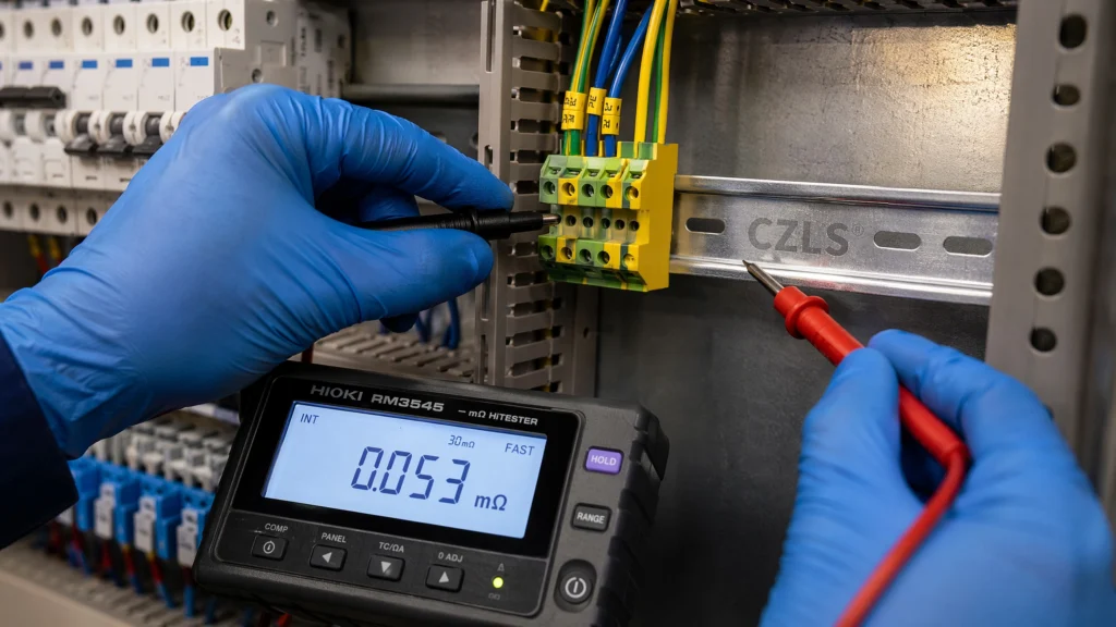
Prepare the mounting surface in accordance with the cabinet, rail, and terminal manufacturers’ instructions. Verify continuity with suitable low-resistance test equipment. The original source mentions specific resistance targets and coating-related resistance values; because no supporting source is provided, the acceptance limit should come from the applicable standard, approved test procedure, or manufacturer documentation. Source needed.
Tightening torque matters as well. Under-tightening can produce an unstable, higher-resistance joint, while over-tightening can damage the conductor or housing. Use the torque stated for the exact part number; the original source’s 0.5-0.8 N·m range for certain 24-12 AWG terminals is not universal and should be verified before use.
Before Installing PE Terminal Blocks, Check:
- The DIN rail surface is conductive and not covered by paint at the required contact area.
- The grounding terminal metal foot makes direct contact with the rail.
- The terminal is tightened according to the manufacturer’s torque specification.
- Continuity is verified with suitable low-resistance test equipment and the approved acceptance criteria.
- Multi-strand wires are properly prepared with ferrules when required by the terminal instructions.
Compliance Considerations: NEC, IEC, and UL
Grounding-terminal selection is governed by the equipment design, installation location, certification scope, and applicable codes. The following summary is for orientation; engineers should confirm the current editions, listing conditions, and local authority requirements for each project.
NEC Grounding Requirements
NEC Article 250 addresses grounding and bonding and requires an effective, continuous fault-current path. Within cabinets and enclosures, the selected termination method must preserve that path. A standard insulated feed-through terminal does not, by itself, bond a PE conductor to the DIN rail or enclosure.
The original article references NEC 250.148 for enclosure grounding connections. Confirm the exact applicability and edition with the project authority having jurisdiction before treating this reference as a design instruction.
IEC 60947-7-2 Requirements
IEC 60947-7-2 covers protective conductor terminal blocks and addresses their mechanical, electrical, and marking characteristics. A PE terminal should be selected as a protective-conductor terminal for the intended rail and conductor range, rather than inferred from appearance alone.
UL 1059 and UL 508A Considerations
UL 1059 covers terminal blocks, while UL 508A applies to industrial control panels within its certification scope. For a listed or certified panel, use components with the appropriate recognition or listing and follow their conditions of acceptability. Do not improvise a PE function with a standard terminal and a field-added jumper unless the approved design and applicable requirements explicitly allow it.
Source Note: The original article included percentages for international-panel use, inspection defects, and other field statistics without traceable citations. Those figures have been omitted from the main claims and should be restored only after the original source is verified.
When Should You Use Grounding Terminal Blocks?
Use grounding terminal blocks where the conductor’s purpose is protective bonding or where the approved design requires a direct low-impedance connection to the cabinet grounding system.
- Protective earth connections
- Motor PE conductors
- Inverter or drive cabinet grounding
- EMC shield termination using the specified shield-grounding accessory
- Surge protection device grounding
For cable shields and surge protective devices, follow the equipment manufacturer’s instructions. Shield bonding, functional earth, and protective earth can have different design requirements even when they share parts of the grounding system.
When Should You Use Standard Terminal Blocks?
Use standard terminal blocks when the purpose is to route operating power, control voltage, or signals between conductors while maintaining electrical isolation from the DIN rail.
- 24 VDC power distribution
- PLC and I/O wiring
- HMI power wiring
- Sensor signal wiring
- Control relay circuits
- Thermocouple and RTD wiring
Application Selection Table
| Application | Recommended Terminal Type | Reason |
|---|---|---|
| Equipment grounding conductor: motor PE or drive chassis | Grounding terminal block | Requires a verified bonding path to the rail and cabinet grounding system |
| Cable shield termination: PROFINET or 4- 20 mA | Specified shield-grounding terminal or clamp | Provides the short, low-impedance shield connection required by the approved EMC design |
| Surge protective device grounding lead | Grounding terminal block | Provides the grounding route specified for surge-current discharge |
| 24 VDC distribution for PLC, HMI, or I/O | Standard terminal block | Transfers operating power without bonding the circuit to the rail |
| Thermocouple or RTD wiring | Standard or application-specific instrumentation terminal | Transfers measurement signals while maintaining the required circuit arrangement |
| Digital I/O or control relay interconnection | Standard terminal block | Routes general control signals |
Common Mistakes to Avoid
- Using standard terminal blocks for PE wires.
- Assuming every DIN rail surface is electrically conductive.
- Installing PE terminals on painted, anodized, contaminated, or oxidized contact areas without an approved preparation method.
- Ignoring the terminal manufacturer’s torque requirements.
- Mixing PE and signal circuits without clear separation, end stops, barriers, or identification.
- Relying only on a basic continuity buzzer test instead of the specified low-resistance verification method.
When troubleshooting a high-resistance grounding path, inspect the terminal-to-rail interface and all rail-to-cabinet bonding points. A four-wire Kelvin resistance test can help remove test-lead resistance from very low-resistance measurements when the approved test procedure calls for it.
Warning: A terminal connection may pass a simple continuity test but still fail under real fault-current conditions if the grounding path has high resistance.
Selection Checklist Before Ordering
- Confirm whether the wire is PE, power, signal, functional earth, or shield.
- Check the applicable standard: NEC, IEC, UL, or local regulations.
- Verify the terminal block type and intended use in the manufacturer datasheet.
- Confirm conductor size, voltage rating, current rating, and connection technology.
- Check whether the product has a conductive metal base for DIN rail grounding.
- Confirm green-yellow PE identification and the protective earth symbol where required.
- Verify compatibility with the selected DIN rail and enclosure bonding design.
- Follow the recommended torque value and conductor-preparation instructions.
- Record part numbers, torque values, and test results for future inspection.
Buyer Check: Do not approve a terminal from its color, shape, or a similar part number. Confirm the exact part number and PE function in the manufacturer’s datasheet.
FAQ
Can I use a standard terminal block for grounding?
No. A standard terminal block usually isolates the conductor from the DIN rail, so it cannot provide the required protective earth path by itself. Use a terminal specifically identified and approved for PE service.
Why are grounding terminal blocks green and yellow?
Green-yellow identifies protective earth connections under applicable IEC wiring-identification practices. The dedicated color helps technicians avoid wiring mistakes during installation, maintenance, and inspection.
Does a grounding terminal block need a conductive DIN rail?
Yes, when the terminal design uses the DIN rail as part of the protective bonding path. Its metal base must contact a suitable conductive rail, and the rail must be properly bonded to the cabinet grounding system.
What happens if the DIN rail is painted?
Paint or powder coating can increase contact resistance or interrupt the grounding path. The required contact area must be conductive or prepared using an approved method, then verified during installation.
What is the main difference between PE terminals and standard terminals?
A PE terminal connects the conductor to the DIN rail and grounding system through a conductive base. A standard terminal transfers power or signal between conductors while remaining isolated from the rail.
Do grounding and standard terminals use different clamping technologies?
Not necessarily. Both types may be screw-clamp, spring-clamp, or push-in. The defining difference is the electrical relationship to the DIN rail, not the clamp style.
Conclusion
Grounding terminal blocks and standard terminal blocks are not interchangeable. The key difference is the grounding path: a PE terminal bonds the protective conductor to the DIN rail and cabinet grounding system, while a standard terminal keeps the operating circuit isolated from the rail.
Correct selection affects safety, compliance, maintainability, and long-term reliability. Engineers and buyers should always verify the exact terminal type, ratings, rail compatibility, markings, and installation instructions in the manufacturer datasheet before ordering or approving a design.