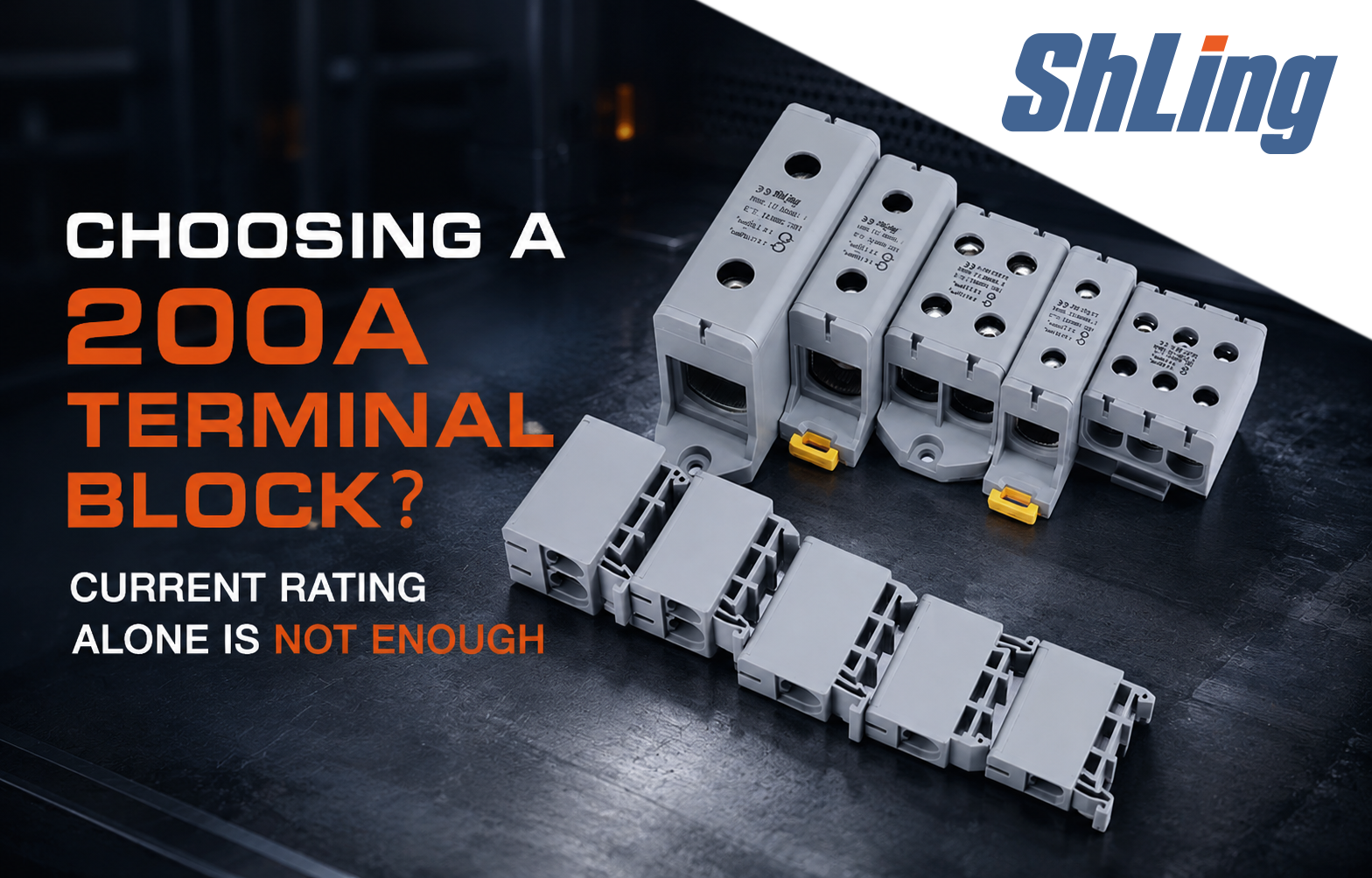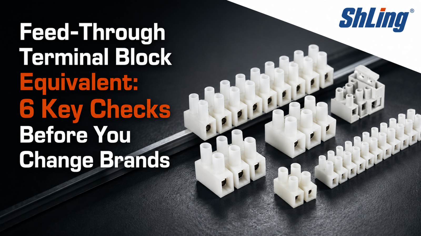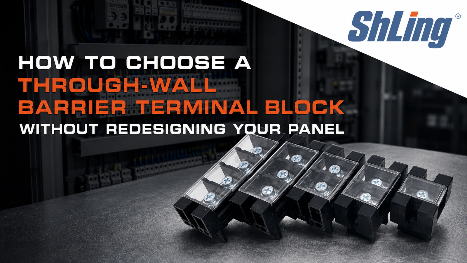
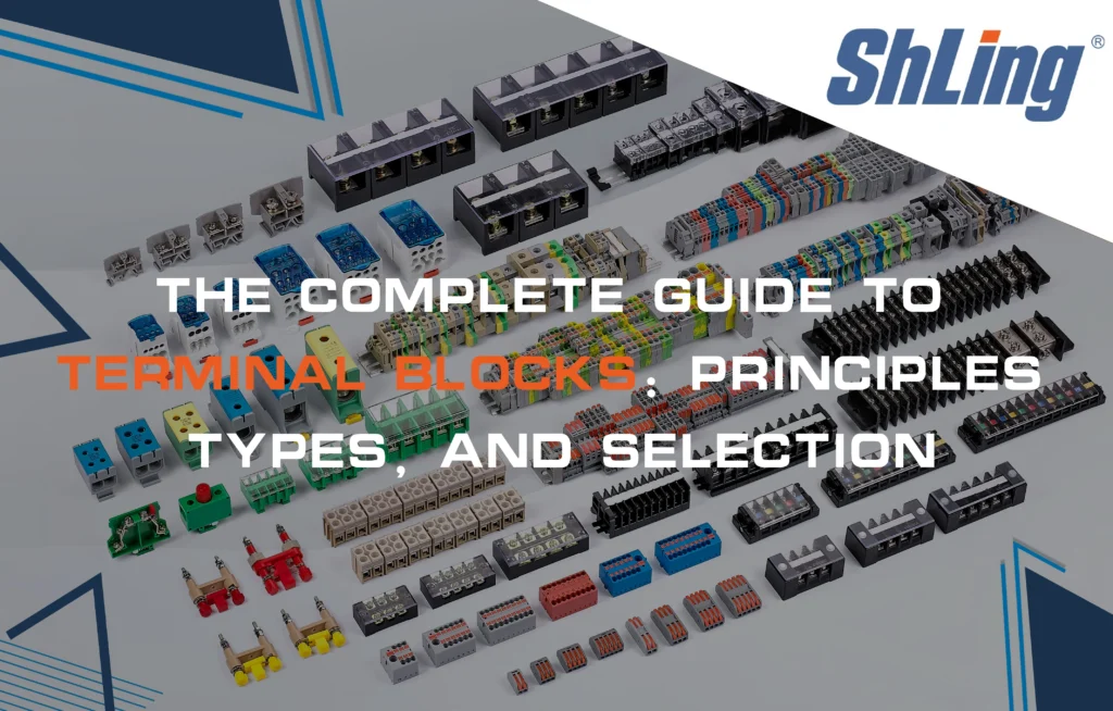
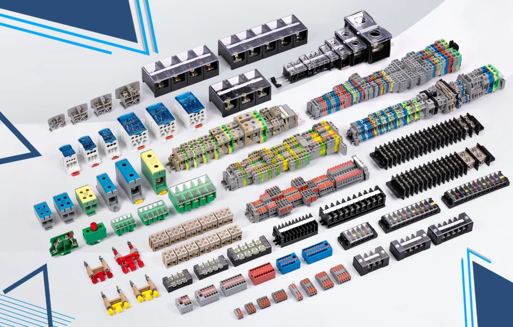
A terminal block is a modular, insulated electrical connector that joins two or more wires together in a safe, organized manner. Also called a connection terminal or terminal strip, it provides a semi-permanent connection point — secure enough for continuous operation in demanding environments, yet removable when inspection, maintenance, or reconfiguration is required. Terminal blocks are found wherever electrical wiring needs to be managed systematically: inside industrial control panels, distribution boxes, motor control circuits, lighting systems, and across factory automation floors.
At its simplest, a terminal block does two things: it connects, and it insulates. The conductive parts carry current between wires, while the insulating housing isolates adjacent circuits, preventing shorts and protecting operators. But that simplicity conceals a wide landscape of types, specifications, and design choices, each suited to a particular set of electrical and mechanical demands. This article unpacks what terminal blocks are, how they work, the main types available, how to specify them, and what to consider when choosing one for your application.
How a Terminal Block Works
Every terminal block, regardless of type, is built around three core components: an insulator, a current-carrying strip, and a clamping mechanism.
The insulator — typically molded from a high-strength, heat-resistant thermoplastic or thermoset resin with a UL94V-0 flame-retardant rating — forms the modular housing. It electrically isolates each connection point from its neighbors and shields live parts from accidental contact. In high-temperature environments, ceramic insulators replace plastic.
The current-carrying strip is the conductive pathway. Made from copper, brass, or corrosion-resistant alloys, it bridges the wire on one side of the terminal to the wire on the other, with minimal resistance and heat generation under load.
The clamping mechanism secures the wire against the current strip. This is where terminal blocks differ most visibly. A screw clamp tightens a metal saddle onto the conductor. A spring clamp uses a preloaded spring force to hold the wire without a screw. A push-in design accepts the wire directly and locks it with an internal spring-loaded lever. IDC (insulation displacement connection) terminals use sharp internal blades that slice through the wire’s insulation and make contact with the conductor — no stripping required.
To make a connection, the installer strips a short length of insulation from the wire end — typically around 12 to 13 millimeters (half an inch) — inserts the bare conductor into the terminal’s port, and tightens or engages the clamping mechanism. The wire is now mechanically fixed and electrically continuous with the current strip and, through it, with whatever is connected on the other side.
Multiple identical terminals are often ganged together into a single assembly called a terminal strip or terminal block strip. In a strip, each terminal remains electrically independent from its neighbors; only the housing is shared. This modularity lets designers build up exactly as many poles as the application requires — anywhere from 2 to 24 or more in a single block.
A Brief History
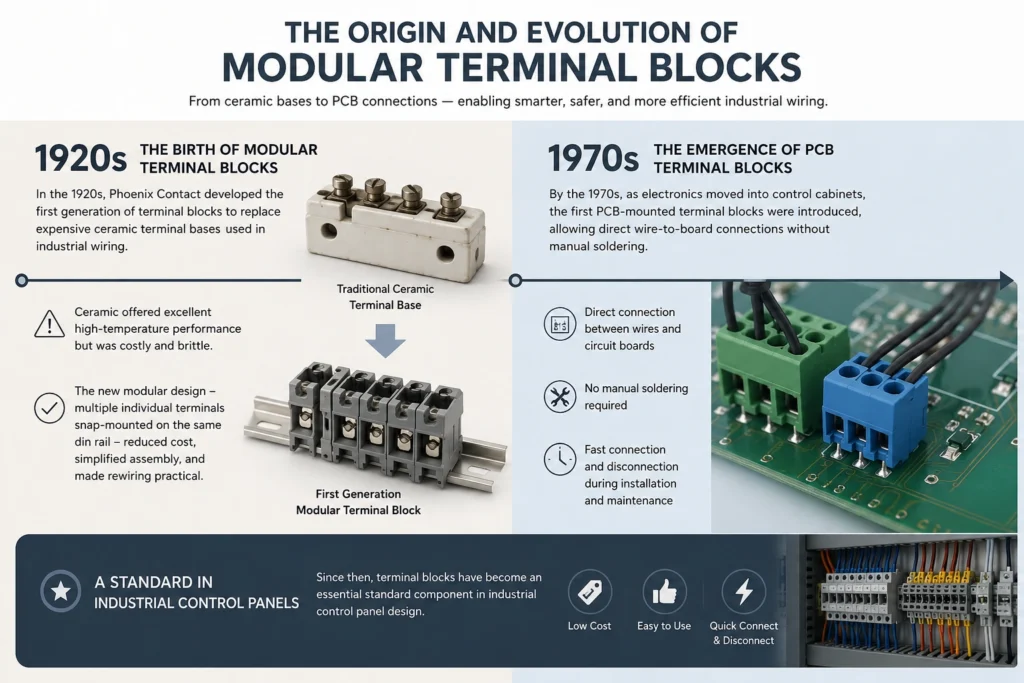
The modular terminal block traces its origin to the 1920s, when Phoenix Contact developed the first generation to replace costly ceramic terminal bases in industrial wiring. Ceramic performed well at high temperatures but was expensive and brittle. The new modular design — individual terminals that could be clipped together onto a shared rail — cut costs, simplified assembly, and made reconfiguration practical.
By the 1970s, as electronics moved into control cabinets, the first PCB-mounted terminal blocks appeared, enabling direct wire-to-board connections without hand-soldering. Since then, terminal blocks have become a staple of industrial control panel design: inexpensive, easy to use, and capable of fast connection and disconnection during commissioning and maintenance.
Types of Terminal Blocks
Terminal blocks can be categorized in three ways: by their structure, by the function they serve in a circuit, and by how they grip the wire.
By Structure
Single-level feed-through terminal blocks are the most basic type. They provide one input contact and one output contact, joined internally by the current strip. Current passes straight through. These are used for simple wire-to-wire connections in signal routing and power distribution, where no circuit protection or isolation is needed at the terminal itself.
Double-level terminal blocks stack a second tier of connections above the first, effectively doubling the connection density within the same footprint on the DIN rail. This saves panel space without sacrificing function. Triple-level blocks add yet another tier on top, and are common in dense control cabinets where every millimeter of rail matters.
By Function
Feed-through blocks (described above) simply pass current from one wire to another. They are the workhorses of panel wiring.
Ground terminal blocks connect the wire — and the block itself — to earth. A metal foot on the bottom of the terminal makes electrical contact with the mounting rail (typically a DIN rail), which is bonded to the panel’s ground system. This eliminates the need to run a separate ground wire from every device back to a central ground bus.
Fuse terminal blocks place a fuse in series with the circuit. The fuse sits in a holder integrated into the terminal body, protecting downstream components from overcurrent. Some designs include a hinged lever that disconnects the circuit when lifted, allowing the fuse to be pulled safely. Others use an LED indicator that lights when the fuse blows, giving maintenance personnel an instant visual cue.
Thermocouple terminal blocks are designed specifically for temperature measurement circuits. Standard terminal blocks introduce a small but problematic thermoelectric voltage at the junction of dissimilar metals — the very effect a thermocouple relies on to measure temperature. Thermocouple blocks use materials matched to the thermocouple type to minimize this error, preserving measurement accuracy.
Multi-level terminal blocks combine structural and functional layering. The bottom level might serve as a feed-through, while the top level houses a fuse or provides a ground connection, all within one compact housing on the rail.
By Connection Method
Screw clamp — the industry standard for decades. A screw drives a pressure plate or saddle onto the wire. It handles a wide range of wire sizes and delivers high clamping force, making it reliable under vibration. The main risk is over-tightening, which can crush or sever stranded conductors. Use the manufacturer’s specified torque.
Spring clamp — a spring-loaded mechanism grips the wire without a screw. Installation is faster and does not require torque control, so it reduces operator error. Spring clamps maintain consistent pressure even as the conductor settles or creeps over time. Many require a ferrule on stranded wire and a release tool (often a small flathead screwdriver) to open the clamp.
Push-in — the wire pushes straight into the terminal and locks behind a spring-loaded lever. A release button or slot beside the entry port lets the operator disengage the lock for removal. Push-in terminals are among the fastest to wire, but some designs are single-use or difficult to rework.
IDC (Insulation Displacement Connection) — internal blades cut through the insulation and bite into the conductor during insertion. No stripping is needed. IDC is the fastest connection method of all, well-suited to high-volume production, but it is generally limited to smaller wire gauges and solid or pre-bonded stranded conductors.
Barrier — heavy-duty blocks with insulating barriers between each pole, connected by screws that clamp ring or spade terminals. Their robust construction handles high current and voltage, and the physical separation between poles reduces the risk of arc-over. Barrier blocks are common in power distribution panels and high-vibration environments.
Stud — wires terminate in ring lugs that bolt onto a threaded stud. The bolted connection withstands severe vibration and thermal cycling without loosening. Stud blocks appear in heavy industrial equipment, generators, and anywhere a mechanically rugged high-current connection is required.
Pluggable — a two-part design: a plug (carrying the wires) and a socket or header (mounted to the rail or PCB). The plug can be disconnected without tools, making pluggable blocks ideal for modules that need to be swapped during service, or for systems that may be reconfigured frequently.
Key Electrical Specifications
Choosing the right terminal block means matching its ratings to the circuit it will carry. The main specifications are orientation, number of poles, pitch, current rating, voltage rating, and wire capacity.
Orientation refers to the angle at which the wire enters the terminal. The three standard directions are 90° (horizontal), 180° (vertical), and 45°. The choice is driven by panel layout and wiring access. A vertically oriented block saves rail width; a horizontal one may simplify wiring in a shallow enclosure.
Poles (contacts, positions, or ways) count the number of independent circuits the block can accommodate. A 3-pole block connects three pairs of wires. Terminal blocks are available from single-pole up to 24-pole configurations and beyond, with manufacturers offering steps in between.
Pitch is the center-to-center spacing between adjacent poles, measured in millimeters. Common pitch values include 2.54 mm, 3.81 mm, 5.0 mm, and 7.62 mm. Pitch directly affects creepage distance (the path an arc would travel along the insulator surface), clearance (the shortest air gap between live parts), and the maximum voltage and current the block can safely handle. A wider pitch generally supports higher voltages.
Current rating specifies the maximum continuous current the block can carry without exceeding its temperature limits. A practical rule of thumb: select a terminal block with a current rating at least 150% of the circuit’s expected maximum steady-state current. This margin accommodates inrush, momentary overloads, and ambient temperature derating.
Voltage rating must exceed the system’s maximum operating voltage, including transient surges. Using a block below its rated voltage risks insulation breakdown and arcing between adjacent poles.
Wire size is given in AWG (American Wire Gauge) or mm². Most blocks accept a range — for example, 24–12 AWG or 4 mm² — giving flexibility in wiring. Verify that the block’s range covers both the conductor cross-section and the type of wire (solid, stranded, or stranded with ferrule) you intend to use.
Mounting Methods
How a terminal block attaches to its enclosure affects installation speed, serviceability, and mechanical robustness.
DIN rail mounting is the most common method in industrial control panels. The terminal block snaps onto a standardized metal rail — typically a 35 mm top-hat DIN rail — and can be slid along it for positioning. DIN rail mounting makes it easy to add, remove, or rearrange blocks as a system evolves. No tools are needed beyond what the terminal itself provides for rail engagement.
Panel mounting uses screws or bolts to fasten the terminal block directly to a flat surface, such as the backplane of an enclosure or a chassis plate. This method provides a rigid, vibration-resistant attachment suited to heavy-duty applications and larger barrier or stud-type blocks.
PCB mounting integrates the terminal block directly onto a printed circuit board, usually through-hole soldered. PCB-mount blocks bridge the internal electronics of a board with external field wiring, and are common in embedded systems, power supplies, and compact automation devices.
Advantages of Using Terminal Blocks
Terminal blocks offer several practical benefits over alternatives like soldered splices, wire nuts, or direct-to-device wiring.
Organization and space efficiency. Terminal blocks impose order on what would otherwise be a tangle of individual wire runs. Neatly aligned on a DIN rail, they reduce clutter, free up panel real estate, and make the wiring legible to anyone who opens the cabinet later. Labels and markers on each block turn the panel into a readable map of the system’s electrical architecture.
Simplified assembly and rework. Connecting a wire to a terminal block requires no solder, no heat, and — depending on the type — no special tool. This speeds up the initial build and makes field modifications straightforward. A technician can add a new sensor or reconfigure a signal path without touching the rest of the wiring.
Electrical safety. The insulating housing encloses live conductors, reducing the risk of shock, accidental short circuits, and arc faults. Well-chosen blocks with proper creepage and clearance distances meet recognized safety standards (UL, IEC) and help the overall panel pass certification.
Maintenance and troubleshooting. A clearly labeled terminal block strip lets a technician isolate a circuit, test voltages, or swap a component without unwiring everything. In a fault situation, the structured layout points directly to the problem area, cutting downtime. For pluggable blocks, the affected module can be disconnected and replaced in seconds.
Versatility and scalability. Terminal blocks accommodate a wide range of wire gauges, current levels, and connection styles within one product family. As system requirements grow, additional blocks clip onto the same DIN rail with no redesign.
Applications
Terminal blocks appear wherever electricity is distributed, controlled, or monitored through wired connections.
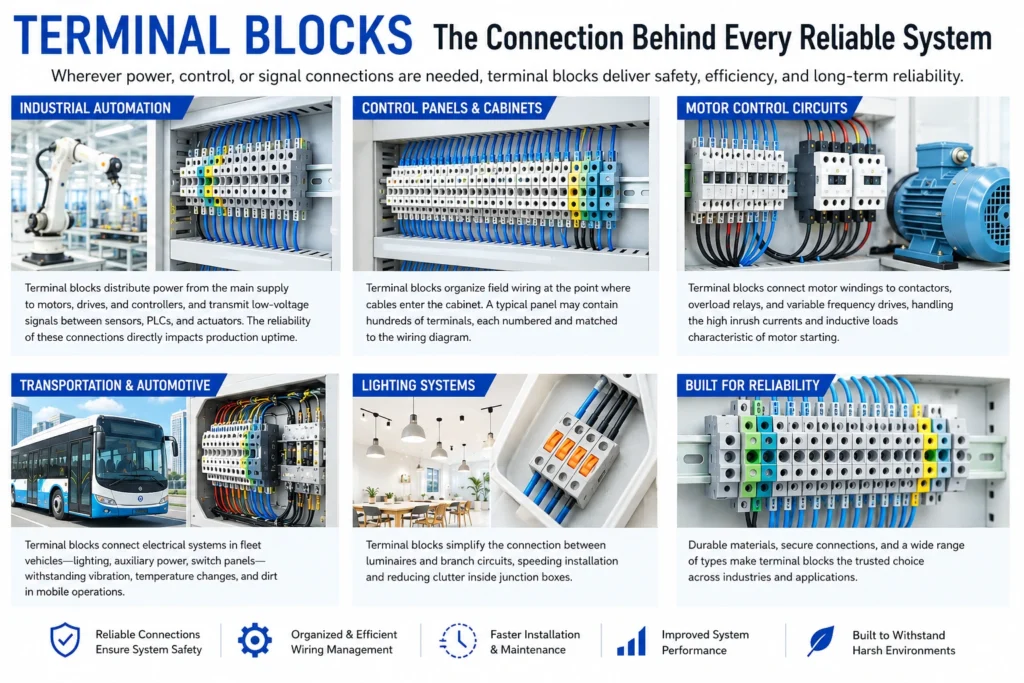
In industrial automation, they route power from main supplies to motors, drives, and controllers, and carry low-voltage signals between sensors, PLCs, and actuators. The reliability of these connections directly affects production uptime.
In control panels and cabinets, terminal blocks organize field wiring where cables enter the enclosure. A typical panel might contain hundreds of terminals, each numbered and cross-referenced to a wiring diagram.
In motor control circuits, terminal blocks connect motor windings to contactors, overload relays, and variable-frequency drives, handling the high inrush currents and inductive loads characteristic of motor starting.
In transportation and automotive applications, terminal blocks connect fleet vehicle electrical systems — lighting, auxiliary power, switch panels — and withstand the vibration, temperature swings, and dirt of mobile operation.
In lighting systems, they simplify the connection of luminaires to branch circuits, speeding installation and reducing junction-box clutter.
How to Choose a Terminal Block
Selecting the right terminal block means evaluating the circuit electrically and mechanically, then matching the block to the environment it will live in.
Current and voltage. Determine the maximum continuous current and peak voltage the block must handle, including transients. Choose a block rated above both, with the 150% current margin noted earlier. Check that the pitch provides sufficient creepage and clearance for the voltage class.
Wire type and size. Confirm that the block accepts the conductor material (copper or aluminum), construction (solid, stranded, fine-stranded), and gauge you are using. If fine-stranded wire is planned, check whether ferrules are required and that the block’s entry accommodates the ferrule diameter.
Environmental conditions. Consider temperature extremes, humidity, dust, chemical exposure, and vibration. In a corrosive atmosphere, specify blocks with nickel-plated current bars or stainless-steel clamping hardware. In high-vibration settings, spring clamp or stud connections resist loosening better than screws. For outdoor or washdown areas, look for blocks with appropriate IP ratings or conformal coatings.
Installation and maintenance access. DIN rail mounting is fast and reconfigurable. Screw terminals are universally understood but require torque discipline. Push-in and spring clamp terminals reduce wiring time but may need specialty release tools. Pluggable blocks pay off where modules are swapped regularly.
Scalability. If the system will grow, choose a modular family that lets you add poles, insert accessory components (end plates, partition plates, jumpers), and bridge across multiple blocks with common accessories.
Standards and certifications. Verify that the block carries the markings required for the installation’s region and industry — UL recognition for North America, IEC ratings for international projects, and any sector-specific approvals (marine, railway, hazardous location) the application demands.
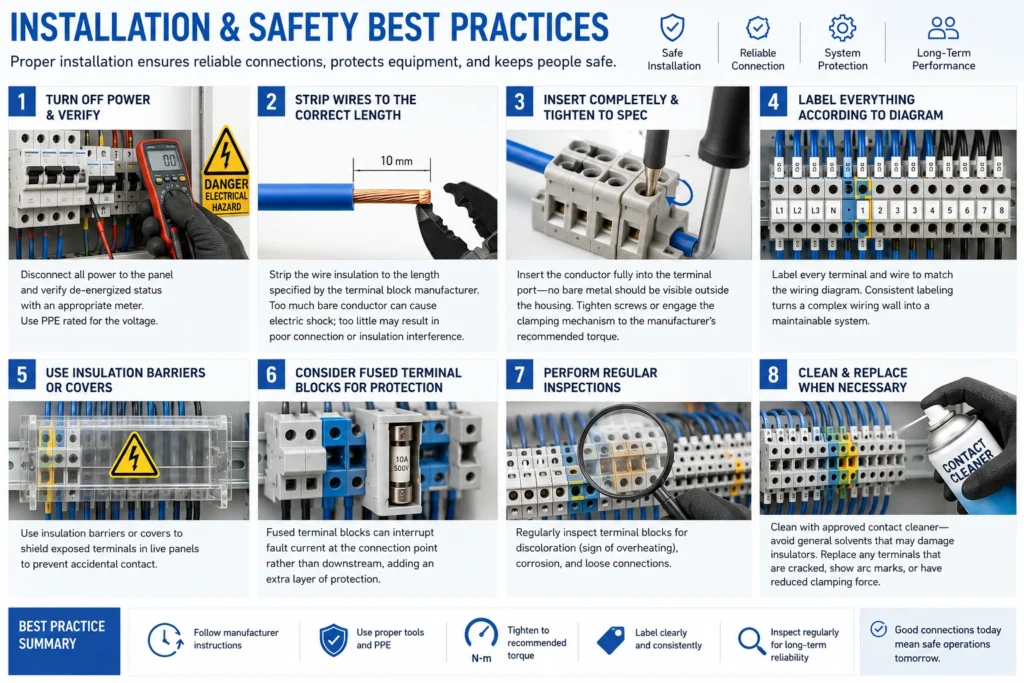
Installation and Safety Best Practices
Safe installation begins before the first wire is stripped. Disconnect all power to the panel and verify with a meter. Use personal protective equipment appropriate for the voltage class.
Strip wires to the length specified by the terminal block manufacturer — exposing too much conductor creates a shock hazard; too little risks a poor connection or clamping onto insulation. Insert the conductor fully into the terminal port so that no bare metal is visible outside the housing, then tighten or engage the clamping mechanism to the manufacturer’s torque specification. For screw terminals, avoid the temptation to give it one more turn — over-tightening is a leading cause of conductor damage.
Label every terminal and wire in a scheme that matches the wiring diagram. Consistent labeling transforms a dense panel from an inscrutable wall of wires into a maintainable system.
In live panels, use insulating partition plates or covers to shield exposed terminals. Fuse-protected terminal blocks add a layer of defense by interrupting fault current at the connection point rather than downstream.
Inspect terminal blocks periodically. Look for discoloration (a sign of overheating), corrosion on metal parts, and loose connections. Clean with approved contact cleaners, not general-purpose solvents that may attack the insulator. Replace any block showing cracks, arc marks, or degraded clamping force.
Troubleshooting Common Issues
Loose connections cause intermittent operation and local heating. Re-tighten screw terminals to specification; for spring or push-in types, remove and re-seat the wire. If the conductor shows signs of cold flow or deformation, trim it back and re-terminate.
Overheating — a block that feels warm to the touch or shows brown discoloration — signals current exceeding the rating, a high-resistance connection, or poor ventilation in the enclosure. Measure the load current, verify the terminal’s rating, redistribute circuits if needed, or upgrade to a higher-rated block.
Corrosion appears as green or white deposits on the current bar or screw. It raises contact resistance and, in severe cases, can cause open circuits. Clean with a contact cleaner and a soft brush. If corrosion recurs, evaluate the environmental seal of the enclosure and consider blocks with corrosion-resistant platings.
Wire misalignment — the conductor sitting beside rather than inside the clamping zone — produces a connection that looks tight but carries no current, or carries it through an unreliable point contact. Re-strip and re-insert the wire, verifying that it enters the port squarely and bottoms out in the terminal.
Conclusion
A terminal block is deceptively simple: a piece of plastic, a strip of metal, and a way to tighten a wire. But that simplicity is the result of a century of refinement, packing high electrical performance, mechanical reliability, and installation practicality into a component small enough to line up by the dozen on a meter of DIN rail.
Understanding the range of types — feed-through, ground, fuse, thermocouple, multi-level — and the trade-offs among connection methods, orientations, pitches, and ratings turns what looks like a commodity part into a considered design decision. The right terminal block, correctly specified and properly installed, keeps a panel safe, serviceable, and ready for whatever the next modification brings.